
Programming instructions


Plug-in Modules Wiring Information 121
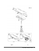
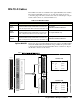
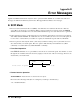
Agilent N2299A Figure 6-29 on Page 121 shows an Agilent N2299A. The wire gauge is 24
AWG (which meets UL AWM: 2464), the maximum voltage is 200 volts per
wire. The connection between the 96-pin female DIN connector and the four
25-pin sub-D male connectors is also listed.
Figure 6-29. Agilent N2299A Cable
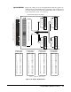
32 31 30 29 28 27 26 25 24 23 22 21 20 19 18 17 16 15 14 13 12 11 10 9 8 7 6 5 4 3 2 1
96-pin female DIN connector (on the DIN-to-D cable)
96-pin male DIN connector (on the plug-in module)
1
14
13
25
CONNECTOR 1
1
14
13
25
CONNECTOR 3
13
1
14
25
CONNECTOR 2
1
14
13
25
CONNECTOR 4
N2299A DIN96-TO-QUAD-D25 CABLE
C
B
A
32 31 30 29 28 27 26 25 24 23 22 21 20 19 18 17 16 15 14 13 12 11 10 9 8 7 6 5 4 3 2 1
C
B
A
CONNECTOR 1
vs. 96-PIN DIN
SUB-D DIN
1
2
3
4
5
6
7
8
9
10
11
12
13
14
15
16
17
18
19
20
21
22
23
24
25
A1
B1
C1
A3
B3
C3
A5
B5
C5
A7
B7
C7
--
A2
B2
C2
A4
B4
C4
A6
B6
C6
A8
B8
C8
Note: A “--” indicates the pin is not used.
SUB-D DIN
1
2
3
4
5
6
7
8
9
10
11
12
13
14
15
16
17
18
19
20
21
22
23
24
25
A9
B9
C9
A11
B11
C11
A13
B13
C13
A15
B15
C15
--
A10
B10
C10
A12
B12
C12
A14
B14
C14
A16
B16
C16
SUB-D DIN
1
2
3
4
5
6
7
8
9
10
11
12
13
14
15
16
17
18
19
20
21
22
23
24
25
A17
B17
C17
A19
B19
C19
A21
B21
C21
A23
B23
C23
--
A18
B18
C18
A20
B20
C20
A22
B22
C22
A24
B24
C24
SUB-D DIN
1
2
3
4
5
6
7
8
9
10
11
12
13
14
15
16
17
18
19
20
21
22
23
24
25
A25
B25
C25
A27
B27
C27
A29
B29
C29
A31
B31
C31
--
A26
B26
C26
A28
B28
C28
A30
B30
C30
A32
B32
C32
CONNECTOR 4
vs. 96-PIN DIN
CONNECTOR 3
vs. 96-PIN DIN
CONNECTOR 2
vs. 96-PIN DIN