
Programming instructions

2 Specifications
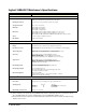
Agilent 3499A/B/C Mainframe’s Specifications
ITEMS SPECIFICATIONS
General
Power Supply: 3499A/B: 100 to 240 VAC universal input; 47 Hz to 440 Hz; 90 VA;
3499C: 100 to 240 VAC universal input; 47 Hz to 63 Hz; 140 VA.
Operating Environment: 0 to 55
o
C (32 to 131
o
F); < 80% RH, 0 to 40
o
C (32 to 104
o
F).
Storage Environment: -40 to +70
o
C (-40 to 158
o
F)
Net Weight: Agilent 3499A: 3.8 kg (8.4 lbs);
Agilent 3499B: 2.5 kg (5.5 lbs).
Agilent 3499C: 7.4 kg (16.4 lbs).
Dimensions: Agilent 3499A (H x W x L): 89mm x 426mm x 348mm (3.5” x 16.8” x 13.7”);
Agilent 3499B (H x W x L): 89mm x 213mm x 348mm (3.5” x 8.4” x 13.7”);
Agilent 3499C
(H x W x L):221.5mm x 426mm x 353.5mm (8.7“ x 16.8“ x 13.9“).
Safety: Conforms to CSA, UL-1244, IEC 1010 Cat I.
RFI and ESD: CISPR 11, IEC 801/2/3/4.
System
Capacity: 5 Slots (Agilent 3499A) or 2 Slots (Agilent 3499B) or 9 slots (Agilent 3499C).
Display: Vacuum fluorescent, 13 characters can be displayed simultaneously.
Rear Panel Connectors: GPIB (IEEE-488); RS-232; 8-pin Mini DIN connector (4-bit Digital I/O, external triggers).
Switch Setting Time: Automatically selected by the mainframe for individual modules;
Additional time from 0 to 99999.999 seconds can be added in 1 ms steps.
Arm Source: External trigger (from the rear panel Mini DIN connector);
IEEE-488 bus (GET, *TRG, or pressing Step from the front-panel);
Software (TRIGger:IMM);
Internal timer (programmable as 0 to 99999.999 seconds in 1 ms steps).
Trigger Source: External trigger (from the rear panel Mini DIN connector);
IEEE-488 bus (GET, *TRG, or pressing Step from the front-panel);
Software (Trigger:IMM); Internal timer (programmable as 0 to
99999.999 seconds in 1 ms steps).
External Trigger Input: Level: TTL compatible; Minimum trigger pulse width: 2 µs;
Maximum external trigger delay
a
: 2 ms.
a. Maximum time from activation of external trigger pulse to start of switch open or close.
External Trigger Output: Level: Normally pull up to 5 V;
Sink current: 10 mA @ V
o
(Low) ≤ 0.4V; 80 mA @ V
o
(Low) ≤ 0.8V;
Low going pulse width: 10 µs typical.
Built-in 4-bit Digital I/O: Input: TTL compatible;
Output: V
o
(high) ≥ 2.4V @ I
o
= 1 mA; V
o
(Low) ≤ 0.8V @ I
o
= −100 mA;
Maximum V
o
= 42V, with external pull-up.
System Speed
b
b. Just for reference. The system speed specification may vary in a small range due to the speed of the remote
PC, the GPIB module, the version of VISA and the version of 3499A/B/C’s firmware used.
Scan Speed: 350 chans/sec (N2266A)
Parser Time
c
:
c. Measured from the time at which the command terminator is taken from the bus to the time at which the relay
begins to open or close.
Open (@100): 3 ms; Close (@100): 3 ms; Open (@100:139): 4 ms
Switching Speed: Channels Time (ms)
Open/Close: 1 7.1 (N2266A)
Open/Close: 10 22.0 (N2266A, in the same group)
Open/Close: 40 28.9 (N2266A)
Digital I/O Block Transfer Rate: 20K bytes/sec (long word)