Legal and Safety Information AGILENT TECHNOLOGIES WARRANTY STATEMENT PRODUCT: Agilent 3499A/B/C Switch/Control System DURATION OF WARRANTY: 1 year 1. Agilent Technologies warrants Agilent hardware, accessories and supplies against defects in materials and workmanship for the period specified above. If Agilent receives notice of such defects during the warranty period, Agilent will, at its option, either repair or replace products which prove to be defective.
Documentation History All Editions and Updates of this manual and their creation date are listed below. The first Edition of the manual is Edition 1. The Edition number increments by 1 whenever the manual is revised. Updates, which are issued between Editions, contain replacement pages to correct or add additional information to the current Edition of the manual. Whenever a new Edition is created, it will contain all of the Update information for the previous Edition.
WARNINGS (Cont.) The Agilent 3499A/B/C can have modules that are capable of switching voltages up to 250V maximum. Voltage levels above the levels specified for accessible connectors or cable ends could cause bodily injury or death to an operator. Special precautions must be adhered to (discussed below) when applying voltages in excess of 60 Vdc, 30 Vac rms or 42.4 Vac peak. Module connectors and test signal cables connected to them cannot be operator accessible.
DECLARATION OF CONFORMITY According to ISO/IEC Guide 22 and CEN/CENELEC EN 45014 Manufacturer’s Name: Manufacturer’s Address: Agilent Technologies (Malaysia) Sdn. Bhd. Bayan Lepas Free Industrial Zone 11900 Penang Malaysia Declares, that the product Product Name: Model Number: Product Options: Switch/Control System and Associated Modules 3499A/B/C This declaration covers all options of the above products.
Contents Agilent 3499A/B/C Switch/Control System Service Manual Legal and Safety Information .......................................................................................... i AGILENT TECHNOLOGIES WARRANTY STATEMENT...................................... i Trademark Information.................................................................................................. i Safety Symbols ............................................................................................................
Chapter 3 Front-Panel Operation ................................................................................................ 31 About This Chapter..................................................................................................... 31 Front-Panel Overview................................................................................................. 32 Display ................................................................................................................
GPIB Test ............................................................................................................ 61 RS-232 Test ......................................................................................................... 61 Keyboard Test ..................................................................................................... 62 Correction ............................................................................................................ 62 Relay Cycle Count .........
Controller ............................................................................................................ 82 Keyboard & Display ............................................................................................ 82 Backplane ............................................................................................................ 83 Chapter 6 Replaceable Parts ......................................................................................................... 85 Introduction...
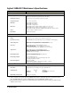
Chapter 1 Specifications General Information The Agilent 3499A/B/C Switch/Control System is composed of three mainframes and a set of plug-in modules. This chapter lists the specifications of the three Agilent 3499A/B/C mainframes and all the plug-in modules. These include: • Agilent 3499A/B/C Mainframes Specifications . . . . . . . . . . Page 2 • Multiplexer (MUX) Modules Specifications . . . . . . . . . . . . Page 3 • GP Relay Modules Specifications. . . . . . . . . . . . . . . . . . . . .
Agilent 3499A/B/C Mainframe’s Specifications ITEMS SPECIFICATIONS General Power Supply: 3499A/B: 100 to 240 VAC universal input; 47 Hz to 440 Hz; 90 VA; 3499C: 100 to 240 VAC universal input; 47 Hz to 63 Hz; 140 VA. Operating Environment: 0 to 55oC (32 to 131oF); < 80% RH, 0 to 40oC (32 to 104oF). Storage Environment: -40 to +70oC (-40 to 158oF) Net Weight: Agilent 3499A: 3.8 kg (8.4 lbs); Agilent 3499B: 2.5 kg (5.5 lbs). Agilent 3499C: 7.4 kg (16.4 lbs).
Plug-in Modules Specifications Multiplexer (MUX) Modules The MUX modules available with Agilent 3499A/B/C include: Agilent N2260A, 44470A/D, N2266A, N2268A and N2270A. Specifications of these MUX modules are listed in the following tables.
ITEMS SPECIFICATIONS Agilent N2266A Agilent N2268A Agilent N2270A 80 1-wire; or 40 2-wire; or dual 20 2-wire; or 20 4-wire Dual 1-to-4 Chans 10 (2-wire) INPUT CHARACTERISTICS Total Channels Maximum Voltage Terminal-Terminal or Terminal-Chassis 200 V, dc or peak AC Resist. 30 V, dc or peak AC Resist. 1000 V peak (per IEC1010 for Pollution Degree I) Maximum Current Per Channel 0.5 A, dc or peak AC Resist. 0.5 A, dc or peak AC 1A Per Module 1 A, dc or peak AC Resist.
ITEMS SPECIFICATIONS Agilent N2266A Agilent N2268A Agilent N2270A Environmental Conditions Operating Pollution Degree 2 Operating Altitude 3000 meters (10,000 ft) Measurement Category I I, 1500 Vpk transient, 500 V over voltage transient Operating Temperature 0-55oC Operating Humidity <80% RH (0oC-40oC), non-condensing a.
Agilent N2272A 1-to-9 RF MUX Module The following table lists the specifications of Agilent N2272A. ITEMS SPECIFICATIONS INPUT CHARACTERISTICS Total Channels 1-to-9 Relay Type Latching Connector Type BNC Maximum Switching Voltage 24VDC Maximum Switching Current 1A Maximum Switching Power 24W Characteristic Impedance 50Ω Relay Life Mechanical Electrical@1A24VDC 5X10⁶ 105 DC CHARACTERISTICS Offset Voltage (mV) 8.0 Initial Closed Channel Resistance (W) 0.
GP Relay Modules The General Purpose (GP) relay modules include: Agilent N2261A, Agilent 44471A/D, Agilent N2264A and Agilent N2267A. Specifications of them are listed in the following tables.
Agilent N2264A GP Relay Module The specifications of the GP relays on an Agilent N2264A are listed in the table below. ITEMS SPECIFICATIONS Agilent N2264Aa Agilent N2264A (12-Channel GP function) (3-Channel High-current GP function) 12 3 INPUT CHARACTERISTICS Total Channels: Maximum Voltage Terminal-Terminal or Terminal-Chassis: 200 V, dc or ac rms 125 V dc or 200 V ac rms Maximum Current Per Channel: 1 A, dc or ac rms 5A, dc or ac rms Maximum Power Per Channel: 60 W dc; 62.
Agilent N2267A GP Module The specifications of Agilent N2267A are listed in the table below. ITEMS SPECIFICATIONS INPUT CHARACTERISTICS Total Channels 8 Maximum Switching Voltage Terminal-Terminal or Terminal-Chassis 250 VAC, 125 VDC Maximum Switching Current Per Channel Per Module 8A 64 A Maximum Switching Power Per Channel Per Module 2000 VA, 150 W 16000 VA, 1200 W Thermal Offset Per Channel 3 mV < 0.
Matrix Modules The matrix modules include: Agilent N2262A 4 x 8 2-wire matrix, Agilent 44473A 4 x 4 2-wire matrix and the 4 x 4 2-wire matrix on an Agilent N2265A. The specifications are listed in the table below.
Digital I/O Modules The digital I/O modules available with Agilent 3499A/B/C include: Agilent N2263A 32-bit digital I/O, Agilent 44474A 16-bit digital I/O module and the 16-bit digital I/O on both the Agilent N2264A/65A multifunction modules. The specifications are listed in the table below.
Agilent N2269A Multifunction Module The following table lists Agilent N2269A module’s specifications. ITEMS SPECIFICATIONS DIGITAL I/O LINES maximum Voltage (line-to-chassis) +5.25 VDC Maximum Sink Current (per bit) 16 mA Maximum Block Transfer Rate Up to 3.57 M by 16 bit/s Output Characteristics Vout (high) Vout (low) >=2.4 V @|<=10 mA output <=0.8 V @|<=16 mA input Input Characteristics Vin (high) Vin (low) >=2.0 V <=0.
Agilent 44472A VHF Switch Module Agilent 44472A VHF Switch module contains 14 latching relays, which provides dual independent 4-to-1 coaxial MUXs. The specifications are listed in the table below.
Agilent 44475A Breadboard Module Agilent 44475A is a breadboard module, and the specifications are listed in the table below. ITEMS SPECIFICATIONS MODULE DIMENTIONS Component Area Available: 104mm x 74mm and 79mm x 74mm (4.1” x 2.9” and 3.1” x 2.9”) Grid Hole Spacing (center-center): 2.54mm x 2.54 mm (0.1” x 0.1”) Grid Hole Size (inside diameter): 1.17mm (0.046”) Maximum Component Height (above board): 12.7mm (0.5”) Maximum lead Length (below board): 3.2mm (0.
Agilent N2276A/B Microwave Switch Module Agilent N2276A’s specifications are listed in the table below. Since the switching and attenuation characteristics of the N2276B are determined by the switches and attenuators installed in it, please refer to the switch’s and/or attenuator’s data sheet for the specifications of your customized N2276B module.
Agilent 44477A Form-C Relay Module Agilent 44477A module provides seven independent, break-before-make, SPDT Form-C latching relays, the specifications of it are listed in the table below.
Agilent 44478A/B 1.3GHz MUX Modules The specifications of the Agilent 44478A/B are listed in the table below. Specifications in the table describe the modules’ warranted performance over the temperature range 0 to 55oC. Information marked by the “Typical” designation is helpful in applying the modules, but is non-warranted information.
Agilent N2280A/N2281A Optical Switch Modules The specifications of the Agilent N2280A/N2281A are listed in the table below. Information in the column “Typical” is helpful in applying the modules. ITEMS SPECIFICATIONS Agilent N2280A Typical Maximum Agilent N2281A Typical Maximum Insertion Loss: Single-mode (SM)a 0.5 dB 0.8 dB 0.5 dB 0.8 dB Return Loss: SMb 50 dB 45 dB (min.) 50 dB 45 dB (min.) Polarization Dependent Loss: SM 0.02 dB 0.07 dB 0.02 dB 0.07 dB Insertion Loss Stabilityc +0.
Agilent N2282A Optical Switch Module The specifications of Agilent N2282A is listed in the table below. ITEMS SPECIFICATIONS Minimum Typical Maximum Channel Count 1-to-8 Switch Type Latching Return Loss (SM)a -62 dB -57 dB Insertion Loss (SM)b 0.5 dB 0.7 dB Insertion Loss Stabilityc ± 0.02 dB Polarization Dependent Loss (PDL) 0.02 dB ± 0.025 dB 0.04 dB Insertion Repeatabilityd Sequential Switching Random Switching ± 0.005 dB ± 0.01 dB ± 0.01 dB ± 0.
20 Specifications
Chapter 2 Getting Started About This Chapter This chapter describes the procedure to install the plug-in modules into a mainframe and mount the mainframe onto a system rack, followed by the basic front panel operations of an Agilent 3499A/B/C Switch/Control System. The chapter contents include: • To Prepare the Instrument for Use . . . . . . . . . . . . . . . . . . . . • Module Installation . . . . . . . . . . . . . . . . . . . . . . . . . . . . . . . . • Operating the Instrument . . . . . . . . . . . . .
Power on the Instrument Make sure no mechanical damages on the instrument, then you can perform the following procedure to verify that the instrument is in proper working order. 1. Connect the instrument to an AC power source with the supplied power cord. 2. Push the Power switch to power on the instrument. 3. On power-up, every segment in the display should light up briefly. The internal self-test will begin following this “starburst” display. 4.
Figure 2-1 on Page 23 shows the procedure to install a plug-in module into the mainframe 3499B, as well as to attach a screw terminal block onto the module. For 3499A, the installation procedure is the same as in 3499B. For the details about screw terminal blocks, crimp-and-insert terminal blocks and/or DIN-to-D cables wiring, see “Plug-in Modules Wiring Information” on Page 110. STEP 1 STEP 2 1. Face the mainframe rear panel towards you; 2. Select a slot in which the module is to be installed. 1.
Operating the Instrument An Agilent 3499A/B/C Switch/Control System can be easily operated from the front-panel, or programmed with SCPI (in SCPI mode) or 3488A (in 3488A mode) commands over the remote interface. The following sections are only intended to show some basic front-panel operation. For more information about the front panel operation, refer to Chapter 3 “Front-Panel Operation” starting from Page 31.
Table 2-1. Plug-in Modules Channel Addressing Channel Addressing Agilent P/N (snn, s = Slot Numbera; nn = Channel Number) Descriptions SCPI Mode Agilent 44478A/B 50/75 W 1.
Table 2-1. Plug-in Modules Channel Addressing Channel Addressing Agilent P/N (snn, s = Slot Numbera; nn = Channel Number) Descriptions SCPI Mode 3488A Mode Agilent N2269A Multifunction Module 16-Bit D/A Port: s40, s42 16-Bit Memory Access Port: S50 Digital I/O: individual Bits: s00, s01,..., s30, s31 8-Bit Port: s00, s01, s02, s03 16-Bit Port: s00, s02 16-Bit D/A Port: s44, s45 16-Bit Memory Access Port: S58 Digital I/O: individual Bits: s00, s01,...
Basic Front-Panel Operation The following examples demonstrate some basic operation to operated the Agilent 3499A/B/C. Assuming that an Agilent N2260A module is installed in slot 1 of the Agilent 3499A and configured as a 40-channel 2-wire MUX (default setting), the channels on the Agilent N2260A can be addressed as 100 through 139. To Open/Close a Channel Turn the knob to the desired channel (i.e. 102), the channel specified is shown on the channel display area.
5. Agilent N2265A Multifunction Module; 6. Agilent N2266A 40-channel 2-Wire MUX Module; 7. Agilent N2267A 8-channel High Current GP Module; 8. Agilent N2268A 50Ω 3.5GHz Dual 1-to-4 MUX Module; 9. Agilent N2270A 10-Channel High Voltage MUX Module; 10.Agilent N2272A 1GHz RF 1-to-9 MUX Module; 11. Agilent N2276A/B Dual 1-to-6(4) Microwave MUX/Atttenuator Module (not include Attenuators); 12.Agilent N2280A/81A/82A Optical Switch Modules.
To Mount an Agilent 3499A To rack mount an Agilent 3499A, the full-rack-width mainframe, order either: • Rack-mount kit with handles, part number 5183-7170, or • Rack-mount kit without handles, part number 5183-7171. Figure 2-2. Rack Mount an Agilent 3499A To Mount an Agilent 3499B To rack mount a single Agilent 3499B, the half-rack-width mainframe, order an adapter kit 5183-7172 (Figure 2-3). This kit includes the flange and filler panel. Figure 2-3.
To rack mount two Agilent 3499B’s side-by-side (or any System II instrument next to an Agilent 3499B), order a Support Shelf 5063-9255 and a slide kit 1494-0015 (Figure 2-5). Figure 2-5. Rack Mount Two Agilent 3499B’s Side-by-Side To Mount an Agilent 3499C To rack mount an Agilent 3499C, order either an adapter kit 5063-9216 (without handles, see Figure below) or 5063-9223 (with handles). Adapter Kit Figure 2-6.
Chapter 3 Front-Panel Operation About This Chapter This chapter introduces you to each front-panel menu, it covers all aspects of front-panel operation. Chapter contents include: • Front-Panel Overview . . . . . . . . . . . . . . . . . . . . . . . . . . . . . . • Local/Remote Control . . . . . . . . . . . . . . . . . . . . . . . . . . . . . • To Monitor a Channel or a Slot. . . . . . . . . . . . . . . . . . . . . . . • To Close or Open a Channel . . . . . . . . . . . . . . . . . . . . . . . . .
Front-Panel Overview The Agilent 3499A/B/C can be operated in either SCPI mode or 3488A mode. All the operations demonstrated in this chapter apply to both modes, unless specifically indicated. % 6:,7&+ &21752/ 6<67(0 5HVHW &DUG 5HVHW 6WRUH 5HFDOO /RFDO 6KLIW 3RZHU 6WRS 6FDQ 0RQ 6WHS &OHDU 6 /LVW 9LHZ 0RGH 2SHQ 5HDG &ORVH :ULWH 0HQX (QWHU Note: 1.
Display % 6:,7&+ &21752/ 6<67(0 . . . . . . . . . . . . ,. ,. ,. ,. ,. ,. ,. ,. ,. ,. ,. ,. As shown in above figure, the display is divided into three areas. Channel area displays the channel/port/slot number. The main display area displays the channel status (open/closed), or other information messages. Around the main display area are the annunciators, as listed in Table 3-1. Table 3-1. Annunciators Summary Annunciator SCAN Scan is initiated. MON Instrument is in monitor mode.
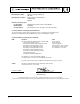
1. Select a slot. Press the two arrow keys to select a desired slot directly, or turn the knob to select the desired slot number. N2260A 1 2. Select a channel. Turn the knob to select a channel (3 digital number). As shown below, the top display indicates the current channel 101 is a MUX channel and in OPEN state, and the lower indicates that the current bit 401 is a digital input port. MUX DIN Note OPEN 101 401 Open, Close, Read and Write keys are invalid if a slot, instead of a channel, is selected.
digital I/O port, or an entire plug-in module. Agilent 3499A/B/C provides you the ability to achieve the above. 1. 2. 3. 4. Press Mon, the MON annunciator lights up; Select the slot or the channel/port to be monitored; Press Enter to display the next part if necessary; Press Mon again to exit the monitoring state, the MON annunciator turns off. Table 3-2. Display on Monitoring Mode Display Description 1:0, , , , , ,6, , ,9, 2 ROW 3: ,1, ,3, , ,6,7 3 0; , ,3,COL 3, 3 00:H255 4 DIO DOUT L254.
To Close or Open a Channel To close/open a channel, you need to: 1. Select the channel to be closed or opened; 2. Press Close/Open to close/open the channel. Repeat steps 1 & 2 to close or open other channels. To Read from a Digital I/O Port To read data from the built-in digital I/O port/bits (090-094), or any one of the 8-bit ports on a digital I/O, you need to: 1. Select a digital I/O port; 2. Press Read to read data from the selected port.
3. Edit the value. Press the two arrow keys to select the to-be-edited bit (in dim), turn the knob to modify the value; DOUT 254 401 4. Press Enter to output the data to the selected port, or press Write again to cancel the current write operation. To Store an Instrument State The Controller board in Agilent 3499A/B mainframe has two types: Controller board Version 1.0 and Version 2.0. Agilent 3499C always has a Controller board of Version 2.0.
Note An instrument reset does not affect the stored instrument setup information. Once a setup is stored, it remains until overwritten or specially deleted with a SCPI command SYSTem:STATe:DELete. Note All the stored instrument setups will be cleared automatically whenever the system mode is changed. To Recall an Instrument State A previously stored instrument setup can be recalled. Before recalling a stored setup, the instrument verifies that all module type and slot assignment match the setup.
of the View menu automatically. NO ERROR 108 If there are errors (the ERROR annunciator is on), the first error in the error queue is displayed. Press the arrow key to scroll the display to show the whole error message; 01:ERR -109 MISSING PARAMETER 3. Turn the knob to view other errors in the error queue, or press Enter to return to the first level of the View menu, the ERROR annunciator turns off; 4. Press View again to exit the View menu operation, the VIEW annunciator turns off.
To View the Relay Cycles To view the relay cycle counts: 1. Press View, the VIEW annunciator lights up. Turn the knob until “RELAY CYCLES” is displayed, then press Enter; RELAY CYCLES 400 2.
Table 3-5. Agilent N2260A Configuration (Mode) 1st level Items 2nd Level Items Description WIRE1 WIRE2 WIRE4 DUAL WIRE2 CONFIG MUX Configure Agilent N2260A Multiplexer module to work as: 80-channel 1-wire, 40-channel 2-wire, 20-channel 4-wire, or two independent groups of 20-channel 2-wire module. • The digital I/O modules can be configured in either SCPI mode or 3488A mode. Table 3-6 on Page 41 shows the Mode key structure. Note The 4-bit built-in digital I/O in Slot 0 cannot be configured.
3. Press Enter, turn the knob to select one mode (i.e. WIRE1); WIRE1 1 4. Press Enter to return to “CONFIG MUX”, press Mode again to exit the configuration, the CONFIG annunciator turns off accordingly. DIO Module Configuration A digital I/O module can be configured, which include the flow control mode, the control line polarity, the flag line polarity, and the I/O direction line polarity. To configure a digital I/O module: 1. Select a slot in which a digital I/O is installed; N2263A 4 2.
7. The instrument returns to “CONFIG DIO”, press Mode again to exit the configuration, the CONFIG annunciator turns off accordingly. DIO Port Configuration To configure the data line polarity and data display format for an individual digital I/O port: 1. Select a digital I/O port (i.e. Port 401), press Mode (the CONFIG annunciator lights up). Turn the knob to select one item (i.e. DATA POLARITY); DATA POLARITY 401 2. Press Enter, turn the knob to select the polarity (i.e.
Stop key Idle Idle Scan key no yes Controlled by Arm Source Arm Layer Another Scan? Controlled by Arm Count Arm Event Detection no Another Channel? yes Controlled by Trigger Source Controlled by Scan List Trigger Event Detection Trigger Layer Output Trigger* Scan Channel * Note: The trigger out pulse will occur at the specified trig-out line only if you have configured to enable the slot to output. Figure 3-2.
Table 3-9. S.List Key Structure in 3488A Mode 1st Level Items 2nd Level Items ADD TO SCAN SELECT nnn DELAY TIME nnnnn.nnn SECS To Create a Scan List Description Create a scan list to include all the desired switch channels, DIO bit channels, and/or the previously stored setups. Set a delay time for all scanned channels. To create a scan list, you can: 1. Press S.List, the CONFIG annunciator lights up, and “ADD TO SCAN” is displayed; ADD TO SCAN 101 2.
value (ranging from 0 to 99999.999 seconds); 00002.000 SECS 3. Use the arrow keys and the knob to set the arm source, press Enter; COUNT: 00003 4. Turn the knob to set the trigger source, then press Enter to return to “CONFIG TO SCAN”; TRIG: MIX If “TRIG:TIMER” is specified, the instrument will guide you to set the time interval (default is 0) after pressing Enter. Use the two arrow keys and the knob to edit or modify the value. Press Enter to set this value (ranging from 0 to 99999.
set its delay time (between 0 and 99999.999 seconds). Press Enter once more to set the delay time and return to “SET CH” item; SET CH 107 SELECT CH 103 00000.005 SECS 103 SELECT CH 103 DELAY TIME 103 4. To set a delay time for other channel, repeat the procedure above. Press S.List again to return to “DELAY TIME”; 5. Press S.List once more to exit this operation, the CONFIG annunciator turns off accordingly. To Start a Scan To start a scan[1]: 1. Press Scan, the SCAN annunciator lights up; 2.
Menu Key Operation Configuring system-related instrument parameters can be done from the Menu key. However, the Menu key structure in 3488A mode (Table 3-10) is different from that in SCPI mode (Table 3-11 on Page 49). Since SCPI mode can do whatever 3488A mode can, only the Menu key operation in SCPI mode will be demonstrated. Table 3-10. Menu Key Structure in 3488A Mode 1st Level Items 2nd Level Items 3rd Level Items 4th Level Items Description FIRST SLOT 1 SECOND SLOT - Pair the same (type) cards.
Table 3-11. Menu Key Structure in SCPI Mode 1st Level Items 2nd Level Items 3rd level Items 4th level Items Description CARD PAIR FIRST SLOT 1 SECOND SLOT - Select the cards to be paired together. CONF EXT TRIG TRIG SLOT 0 ENABLE DISABLE Select a pair of external trigger lines and enable/disable Agilent 3499 to output a trigger pulse. PWR ON RESET Set instrument power-on to the reset state or a state stored in memory location nn.
To Pair Two Cards Two same type plug-in modules (cards) can be paired. Once paired, any operation on a channel of one module will be duplicated on the corresponding channel of the paired module. To pair two same type cards: 1. Press Menu, the CONFIG annunciator lights up. Turn the knob to select “CARD PAIR”, press Enter; CARD PAIR 2. When “FIRST SLOT 1” is displayed, turn the knob to select the first paired slot (i.e. Slot 1), then press Enter[1]; FIRST SLOT 1 3.
3. To enable a trigger pulse output from the selected line, turn the knob to select “ENABLE”; or select “DISABLE”; ENABLE 4. Press Enter, the instrument returns to “CONF EXT TRIG”. Press Menu again to exit this operation, the CONFIG annunciator turns off accordingly. Note To Configure the Power-on State[1] In SCPI mode, once a new pair of control lines is selected, the newly selected trigger-in line is immediately ready to accept the trigger signal from an external instrument.
3. Press Menu again to exit this operation, the CONFIG annunciator turns off accordingly. 52 Note Please note that the content in this section is only effective for Agilent 3499A/B/C mainframe with Firmware REV 4.0 or later. for Agilent 3499A/B with Firmware REV1.0/2.0/3.0, please ignore this section.
To Configure the Remote Interface The instrument can communicate with a computer over GPIB or RS-232 interface. Perform the following procedure to configure the interface. Note Only one interface can be used at a time. When shipped from the factory, the GPIB interface is selected and its address is set to “9”. Note RS-232 interface can be configured and used only in SCPI mode. GPIB Interface 1. Press Menu, the CONFIG annunciator lights up.
4. Turn the knob to select the parity and data bits (default: NONE, 8 BITS), then press Enter; NONE; 8 BITS 5. Turn the knob to select the mode (default: FLOW NONE), then press Enter to return to “INTERFACE”; FLOW NONE 6. Press Menu again to exit this operation, the CONFIG annunciator turns off accordingly. To Perform a Self-test The self-test feature of the instrument can be used to verify proper instrument operation. To perform a self-test: 1. Press Menu, the CONFIG annunciator lights up.
2. Turn the knob to select the system mode, press Enter; HP 3488A MODE 3. The instrument will be reset if the system mode has been switched; or it will display “SYSTEM MODE”. In later case, press Menu again to exit this operation. To Query the Firmware Revision To query the Agilent 3499A/B/C firmware revision: 1. Press Menu, the CONFIG annunciator lights up. Turn the knob to select “REVISION INFO”, then press Enter; REVISION INFO 2.
To Query the Serial Number To query the Agilent 3499A/B/C serial number: 1. Press Menu, the CONFIG annunciator lights up. Turn the knob to select “SERIAL NO”; SERIAL NO 2. Press Enter, Agilent 3499A/B/C serial number is displayed; CN12345678 3. Press Enter to return to “SERIAL NO”, press Menu again to exit this operation, the CONFIG annunciator turns off accordingly.
To Reset a Module To reset a plug-in module: 1. Turn the knob to select the slot to be reset; N2260A 1 2. Hold down Card Reset until the display changes from “HOLD TO RESET” to “RESET CARD”, then release the key to end this operation. Note HOLD TO RESET 1 RESET CARD 1 N2260A 1 Card Reset will open all channels on the switching module and make all ports on the specific digital I/O module as input ports. To Reset the Instrument To reset the instrument: 1.
58 Front-Panel Operation
Chapter 4 Verification Tests About This Chapter This Chapter contains procedures for operating verification of the Agilent 3499A/B/C mainframes and the plug-in modules. This Chapter contains the following sections: • General Information . . . . . . . . . . . . . . . . . . . . . . . . . . . . . . . • Mainframe Self-Test . . . . . . . . . . . . . . . . . . . . . . . . . . . . . . . • Mainframe Verification Tests . . . . . . . . . . . . . . . . . . . . . . . . • Relay Cycle Count . . . . . . . . . . . . . .
WARNING Hazardous voltages may exist on the wiring and connectors of the Agilent 3499A/B/C plug-in modules. Only service trained personnel should make repairs to the Agilent 3499A/B/C mainframes and/or the plug-in modules. WARNING Make sure to disconnect all the wiring from the Agilent 3499A/B/C plug-in modules to the external devices in order to execute the Verification Tests.
Table 4-1. Error Number Correction Description +3 RS-232 test failed. +4 Front-panel test failed. If, during the display test, a segment or segments malfunctioned, a problem exists on the Controller board or the Display assembly. Refer to “Agilent 3499A/B/C Problem Isolation” on Page 80 for problem isolation information. If the front-panel test failed, a problem exists on the front panel circuitry; if any of the other internal tests failed, the Controller board is malfunctioned.
If “RS232 TEST” is displayed on the front panel of the Agilent 3499A/B/C, the RS-232 test passed. Otherwise, the RS-232 test failed. Keyboard Test All the keys on the front panel of an Agilent 3499A/B/C can be tested easily by pressing the keys. If one or more keys has no response, a problem exists in either the Keyboard Assembly, or the Controller board. Refer to “Agilent 3499A/B/C Problem Isolation” on Page 80 for problem isolation information.
MUX module’s removable wiring terminal block as shown in Figure 4-1. 72 08; 02'8/( 73 &20 73 7(67 ),;785( :,5,1* :,5,1* 7(50,1$/ %/2&. Figure 4-1. MUX Modules Test Fixture The fixture contains: n A short circuit between all of the low (L) lines (TP1); n A short circuit between all of the high (H) lines (TP2); n A short circuit between the shorted common lines (COM). With the test fixture installed, and a Multimeter (i.e.
3499A/B/C and the Multimeter. The Agilent 3499A/B/C’s display should show a number corresponding to the closed relay. The clumsy damaged relay(s) can be isolated in this way. Correction If during Step 8, one or more relays did not close as described, a problem exists either in the Controller board or the related MUX module. Replace this MUX with another same one and perform the tests as described above to isolate the problem.
With the test fixture installed, and a Multimeter (i.e. an Agilent 34401A) connected between the shorted low lines (TP1) and the shorted high lines (TP2), the GP Relay module is tested by successively closing each relay while checking for an indication of the closure on the Multimeter. Tests Procedure Note To perform the Operation Verification Tests: 1. Remove the wiring terminal block from the GP Relay module; 2. Install the related test fixture onto the GP Relay module; 3.
module’s removable wiring terminal block as shown in Figure 4-3. 72 0$75,; 02'8/( 1 $ $ 1 $ 0DWUL[ )XQFWLRQ 52: &2/801 :,5,1* 7(50,1$/ %/2&. 7(67 73 73 73 73 ),;785( :,5,1* Figure 4-3.
8. Successively press Step while observing the displays on the Agilent 3499A/B/C and the Multimeter. The Agilent 3499A/B/C’s display should show a number corresponding to the closed relay. The clumsy damaged relay(s) can be isolated in this way. Correction If during Step 8, one or more relays did not close as described, a problem exists either in the Controller board or the related Matrix module. Replace this Matrix with another same one and perform the tests as described above to isolate the problem.
72 ',2 02'8/( :,5,1* 7(50,1$/ %/2&. CHAN CLOSED* GND PCTL/RD H7 H6 H5 H4 H3 H2 H1 H0 L7 L6 L5 L4 L3 L2 L1 L0 IO/WR GND PFLG/EXT INC 7(67 ),;785( :,5,1* PCTL/RD IO/WR GND 7KH OLQH &+$1 &/26(' RQO\ H[LVWV RQ WKH $ ELW ',2 IRU 1 $ ELW ',2 DQG 1 $ $ ELW ',2 PRGXOHV WKLV OLQH GRHV QRW H[LVW Figure 4-4. DIO Modules Test Fixture This fixture is applicable for the Agilent 44474A 16-bit DIO.
module should be input (DIN). Press Mon, the display should be “DIN 11111111 snn” or “DIN 255 snn”, where s = slot number, and nn is the related port number; 3. Write a binary 10101010 to any one of the 8-bit ports (in order to open every other line) and verify the data has been transferred to all the other ports. Take an Agilent N2263A for example, if a data (10101010) has been written to the port s02, this data should be transferred to other ports s00, s01 and s03.
Correction Replace the DIO module with a new one if it is failed. Agilent 44472A Verification Tests The VHF Switch module consists of two 4-to-1 MUXs with BNC connections. Only the center conductor of each channel is switched. The outer conductors (shield) of all channels in a particular MUX are connected together and unswitched. Tests Procedure To test a channel: 1. Remove any external wiring from the rear of the 44472A. Reset the 44472A and press Mon; 2.
Coaxial Switches; these coaxial switches come in 3/4/5-port configurations. To verify that the 33311B Coaxial Switches on the Agilent 44476A (or the switches you provide on the Agilent 44476B) are functioning, verify continuity between the common port and the port connected to it. Also, verify there is no continuity between the common port and any unconnected ports.
4. Repeat Steps 2 & 3 to verify the other channels; 5. Close all the channels on the Agilent 4476A/B; 6. Verify continuity between the Channel 00 center conductor of the common port and center conductor of port 2. For an Agilent 44476B, you must determine which ports should have continuity for Channel 00 and verify it; 7. Verify there is no continuity between the common port and port 1 of channel 00. For the Agilent 44476B, you must determine which ports should not have continuity and verify they do not; 8.
properly. TO 44477A CH00 CH01 CH02 CH03 CH04 CH05 CH06 NO C NC NO C NC NO C NC NO C NC NO C NC NO C NC NO C NC WIRING TERMINAL BLOCK TEST FIXTURE Figure 4-6. Agilent 44477A Test Fixture To Verify the NO Contacts: 1. Connect a Multimeter between TP1 (C) & TP2 (NO), reset the Agilent 44477A. The Multimeter should show an open circuit; 2. Close Channel 00 and check the Multimeter for an indication of closure.
Agilent 44478A/B Verification Tests Agilent 44478A/B consists of two 4-to-1 MUXs (Group 00 & Group 10) that can switch signals bidirectionally. Each group has a separate ground for isolation between groups and this ground is unswitched (Figure 4-7). To verify that the relays in each group are functioning, verify continuity between the center conductor of the common BNC and each channel’s BNC center conductor when that channel is closed.
Tests Procedure To verify that the relays in each group are functioning: 1. 2. 3. 4. 5. 6. 7. 8. 9. Correction Remove any external wiring from the Agilent 44478A/B connectors; Reset the Agilent 44478A/B and press Mon; Create a scan list including all the channels on an Agilent 44478A/B; Connect the Multimeter between the center conductor of the COM 00 connector and the center conductor of the channel under test (start with CH 00).
Agilent N2280A/81A/82A Verification Tests Agilent N2280A consists of four 1-to-2 Optical Switches, each 1-to-2 Optical Switch should be tested independently. Agilent N2281A consists of two 1-to-4 Optical Switches, each 1-to-4 Optical Switch should be tested independently. Agilent N2282A consists of one 1-to-8 Optical Switch.
Test Procedure Before testing the Agilent N2280A/81A/82A Optical Switch Module, the user should have an Optical Multimeter in hand. When testing, the two Optical probes of the Optical Multimeter should be connected to the two end-connectors of one channel of the specific Optical Switch, then execute closing and opening commands on it , you can find whether this channel is normal or not via the optical multimeter’s display. To verify that the optical switches in each group are functioning: 1.
78 Verification Tests
Chapter 5 Service Introduction This Chapter provides general service related information about the Agilent 3499A/B/C Switch/Control System. This includes safety considerations, static-handling procedures, and problem isolation processes. Chapter contents include: • Safety Considerations . . . . . . . . . . . . . . . . . . . . . . . . . . . . . . • Static Handing. . . . . . . . . . . . . . . . . . . . . . . . . . . . . . . . . . . . • Agilent 3499A/B/C Problem Isolation . . . . . . . . . . . . . . . . .
Any assembly or subassembly removed from the mainframe MUST be handled in accordance with anti-static handing procedures. The following guidelines are the minimum requirements for a static safe service environment. • The work bench should be equipped with a conductive table mat. The mat should be grounded to earth ground through a 1 MΩ resistor. The mat should be equipped with at least one swivel connected to the swivel connector for connecting wrist straps.
the problem is mostly on the mainframe; if the problem is solved, the problem may be caused by one or more plug-in module. Plug-in Module Substitution The easiest and fastest method to isolate a failure to a particular assembly is the board substitution technique. The technique calls for the suspected bad board to be replaced with a known good board. If the problem is solved, the replaced board or assembly had the problem. A limited substitution may be performed to isolate a faulty plug-in module.
are incorrect, check the cable (03499-61004) and the plug-in modules. You can perform more tests to further isolate the problem to the cable, or the particular plug-in module. 03499-61007 03499-61004 J1 Pin 1 Pin 2 Pin 3 Pin 4 Pin 5 Pin 6 J2 Pin 1 AC Line Pin 2 AC Neutral 03499-61002 J3 (Safety Ground) +12V +5.1V +5.1V Return Return -12V Fuse 3.15A, 250 VAC Figure 5-1.
Parts” on Page 85). Keyboard & Display 03499-40003 (for 3499B) 03499-40001 (for 3499A) 03499-60001 03499-40008 (for 3499A) Keyboard & Display Kits 03499-40009 (for 3499B) 34970-87401 03499-40005 5041-0564 3051-1941 0535-0154 Figure 5-2. Keyboard & Display on an Agilent 3499B Backplane If a plug-in module will not function in only one slot, the backplane board should be suspected.
Controller board failure. 03499-60002 (for 3499B) 0515-0664 03499-60003 (for 3499A) 03499-00005 (for 3499B) Figure 5-3.
Chapter 6 Replaceable Parts Introduction This Chapter contains the disassembly/assembly procedures for an Agilent 3499A/B/C mainframe, followed by the mechanical and electrical replaceable parts for the Agilent 3499A/B/C mainframe, and its plug-in modules. This Chapter contains the following sections: • Agilent 3499A/B/C Disassembly/Assembly Procedures . . . • Agilent 3499A/B Mainframe Replaceable Parts. . . . . . . . . . • Agilent 34399C Mainframe Replaceable Parts. . . . . . . . . . .
STEP 1: Front-Panel Removal 1. 4. 2. 5. 6. 3. a. c. b. d. 7. 8. Figure 6-1. Front-Panel Removal Figure 6-2 shows the Front-Panel disassembling procedures. e. g. f. h. Figure 6-2.
STEP 2: Cover Removal 9. 10. 11. 12. a. b. Figure 6-3. Cover Removal STEP 3: Power Supply Removal 13. 14. a. 15. 16. b. 17. 18. 19. Figure 6-4.
STEP 4: Controller board Removal 20. 21. 22. a. 23. c. 24. b. d. 25. 28. 29. 30. 31. Figure 6-5. Controller board Removal 88 Replaceable Parts 26. 27.
STEP 5: Rear Bezel Removal 34. 33. Figure 6-6. Rear Bezel Removal STEP 6: Backplane Removal 35. 36. 37. a. 38. b. 39. 40. 41. Figure 6-7. Backplane Removal 3499A/B Assembly Procedures To assemble an Agilent 3499A/B mainframe, reverse the procedures above.
3499C Disassembly Procedures STEP 1: Top Cover and Front Panel Removal 1. 2. a. c. b. d. 3. 9. 4. 5. 6. 7. 8. STEP 2: Backplane Shield, Power Module, Power Protection Module and Controller Board Removal. 10 . 11. a. c. b. d. 12. 13. 14.
STEP 3: Backplane Removal. a. b. 3499C Assembly Procedures To assemble an Agilent 3499C mainframe, reverse the procedures above.
Agilent 3499A/B Mainframe Replaceable Parts Table 6-1. Agilent 3499A/B Mainframe Replaceable Parts Part Number ITEM # 1 Qty.
Table 6-1. Agilent 3499A/B Mainframe Replaceable Parts Part Number ITEM # Qty. 3499A DESCRIPTION 3499B 30 0515-0367 2 SCR-MACHINE 31 0380-0643 2 STDF-HEX .
Agilent 3499C Mainframe Replaceable Parts Table 6-2. Agilent 3499C Mainframe Replaceable Parts 94 ITEM # Part Number Qty.
Plug-in Modules Replaceable Parts Table 6-3 lists the replaceable parts for the existing Agilent 3499A/B/C plug-in modules. Kits 1 through Kits 6 are used to refer to the different sets of mechanical kits as described in the follow-up sections. Table 6-3.
Table 6-3. Plug-in Modules Replaceable Parts Product Number PCA (P/N) Mechanical Kits Microwave Module Agilent N2281A N2281-60001 Kits 13 None Agilent N2282A N2282-60001 Kits 14 None a. The microwave modules used with an Agilent 44476B can be the 3-, 4- or 5-port modules (8762A/B/C/F, 8763B/C, 8764B/C), from DC to 26.5 GHz, and must be ordered separately.
Mechanical Kits 1 & 2 Figure 6-8 shows the replaceable mechanical parts for Kits 1 & 2 as listed in Table 6-4. MP49 (1 EA) MP52 (4 EA) MP51 (2 EA) MP48 (1 EA) MP50 (2 EA) Figure 6-8. Mechanical Kits 1 & 2 Table 6-4. Mechanical Kits 1 & 2 Ref. Designation Qty. MP48 1 MP49 Description Kits 1 (P/N) Kits 2 (P/N) SHIELD CIRCUIT 03488-00612 5184-0501 1 SHIELD COMP 03488-00613 5184-0502 MP50 2 PC EXTRACTOR WHT 0403-0464 MP51 2 PIN-GRV 3/32 X 1/4 1480-0625 MP52 4 SCREW M3.
Mechanical Kits 3 44472A Figure 6-9 shows the replaceable mechanical parts (Kits 3) as listed in Table 6-5. MP53 (4 EA) MP55 MP59 MP57 (4 EA) MP56 (2 EA) MP54 MP61 (2 EA) MP60 (2 EA) MP58 Figure 6-9. Mechanical Kits 3 Table 6-5. Mechanical Kits 3 98 Ref. Designation Qty. MP53 4 SCREW M2.
Mechanical Kits 4 & 5 44476A Figure 6-10 shows the replaceable mechanical parts (Kits 4 & 5) as listed in Table 6-6 on page 100. SCW1-4 Kits4 SHD1 SCR1-6 SHD2 PNL1 44476B SCW1-4 Kits5 SCR1-4 SHD1 SCR7-8 WSH1-2 SHD2 PNL2 Figure 6-10.
Table 6-6. Mechanical Kits 4 & 5 Ref. Designation Qty. Description SW1 1 SW2 1 SW3 1 SCR1 1 SCR2 1 SCR3 1 SCR4 1 SCR5 1 SCR6 1 SCW1 1 SCW2 1 SCW3 1 SCW4 1 SHD1 1 SHIELD - CIRCUIT SIDE 44476-00601 SHD2 1 SHIELD - COMPONENT SIDE 44476-00602 PNL1 1 PANEL - Agilent 44476A 44476-00201 PNL2 1 PANEL - Agilent 44476B 44476-00202 SCR7 1 0515-0905 SCR8 1 SCREW-PANHEAD M2.5 X 6mm LONG WSH1 1 2190-2583 WSH2 1 WASHER-LOCK HLCL 2.5 MM 2.
Mechanical Kits 6 Figure 6-11 shows the replaceable mechanical parts (Kits 6) as listed in Table 6-7. SCW1 (16 EA) 44478A/B SHD1 SHD2 MP2 MP1 Figure 6-11. Mechanical Kits 6 Table 6-7. Mechanical Kits 6 Ref. Designation Qty. Description MP1 1 BRACKET - LEFT 44478-41201 MP2 1 BRACKET - RIGHT 44478-41203 SCW1-16 16 SCREW-MACH M3.0 X 0.
Mechanical Kits 7 Figure 6-12 shows the replaceable mechanical parts (Kits 7) as listed in Table 6-8. N2267A SCW1 SHD1 SHD2 PNL1 Figure 6-12. Mechanical Kits 7 Table 6-8. Mechanical Kits 7 Ref. Designation Qty. PNL1 1 FRONT-PANEL SCW1 4 SCRFHM2.
Mechanical Kits 8 Figure 6-13 shows the replaceable mechanical parts (Kits 8) as listed in Table 6-9. N2268A SCW1 SHD1 SHD2 PNL1 Figure 6-13. Mechanical Kits 8 Table 6-9. Mechanical Kits 8 Ref. Designation Qty. PNL1 1 FRONT-PANEL 1 SCREW M3.0-FLAT (SHEET METAL) 0515-1946 2 SCRFHM2.
Mechanical Kits 9 Figure 6-14 shows the replaceable mechanical parts (Kits 9) as listed in Table 6-10. SCW1 N2270A SHD1 SHD2 PNL1 Figure 6-14. Mechanical Kits 9 Table 6-10. Mechanical Kits 9 Ref. Designation Qty. PNL1 1 FRONT-PANEL SCW1 8 SCREW M3.
Mechanical Kits 10 Figure 6-15 shows the replaceable mechanical parts (Kits 10) as listed in Table 6-11. N2272A SHD1 SHD2 PNL1 Figure 6-15. Mechanical Kits 10 Table 6-11. Mechanical Kits 10 Ref. Designation Qty.
Mechanical Kits 11 Figure 6-16 shows the replaceable mechanical parts (Kits 10) as listed in Table 6-12. N2276A/B SHD2 SHD1 PNL1 Figure 6-16. Mechanical Kits 11 Table 6-12. Mechanical Kits 11 Ref. Designation Qty.
Mechanical Kits 12 N2280A Figure 6-17 shows the replaceable mechanical parts (Kits 10) as listed in Table 6-13. SCW1 SHD1 SHD2 PNL1 Figure 6-17. Mechanical Kits 12 Table 6-13. Mechanical Kits 12 Ref. Designation Qty. Description Part Number PNL1 1 FRONT-PANEL SCW1 8 SCREW M3.
Mechanical Kits 13 N2281A Figure 6-18 shows the replaceable mechanical parts (Kits 11) as listed in Table 6-14. SCW1 SHD1 SHD2 PNL1 Figure 6-18. Mechanical Kits 13 Table 6-14. Mechanical Kits 13 Ref. Designation Qty. PNL1 1 FRONT-PANEL SCW1 8 SCREW M3.
Mechanical Kits 14 Figure 6-19 shows the replaceable mechanical parts (Kits 14) as listed in Table 6-15. N2282A SHD2 SHD1 PNL1 Figure 6-19. Mechanical Kits 14 Table 6-15. Mechanical Kits 14 Ref. Designation Qty.
Appendix A Plug-in Modules Wiring Information BNC and SMA Connection The modules listed in Table 6-16 provide BNC or SMA connections to external devices. Table 6-16. BNC & SMA Connection Connection Type Quantity Module Description 10 Agilent 44472A Dual 4-Channel VHF Switch Module 10 Agilent 44478A 50Ω 1.3 GHz MUX Module 10 Agilent 44478B 75Ω 1.
Table 6-17. Screw Terminal Blocks Screw Terminal Block (Wiring Inf.) Type C[2] (Figure 6-23 on Page 115) Agilent P/N Application Agilent N2290A For Agilent N2260A module only. Agilent N2291A For Agilent N2261A module only. Agilent N2292A For Agilent N2262A module only. Agilent N2293A For Agilent N2263A module only. Agilent N2294A For Agilent N2264A module only. Agilent N2295A For Agilent N2265A module only. Agilent N2329A For Agilent N2269A module only. [1].
Screw Terminal Block Wiring (Type A) Figure 6-20.
Figure 6-21.
Screw Terminal Block Wiring (Type B) 'HWHUPLQH WKH ZLUHV WKH ZLUH H[LW 5HPRYH FRYHU $ 7KH ZLUH JDXJH $:* % :LUHV FRQQHFWHG WR 3 3 H[LW IURP (;,7 & :LUHV FRQQHFWHG WR 3 3 H[LW IURP (;,7 $ 5HOHDVH VFUHZ RQ WRS RI WKH FRYHU % 3UHVV WDE IRUZDUG DQG UHOHDVH - 3 3 3 3 (;,7 (;,7 5HSODFH FRYHU $WWDFK ZLUHV $ ,QVHUW ZLUH LQWR WHUPLQDO FRQQHFWRUV % 7LJKWHQ VFUHZV RQ WKH FRQQHFWRUV & 7LJKWHQ ZUDSV WR VHFXUH
Screw Terminal Block Wiring (Type C) 67(3 5HPRYH FRYHU $ 5HOHDVH VFUHZV RQ WRS RI WKH FRYHU % 3UHVV WDE IRUZDUG DQG UHOHDVH 67(3 7LJKWHQ WKH ZLUHV $ ,QVHUW WKH ZLUHV LQWR WKH QHDUHVW FDEOH ERRW PRYH WKH FDEOH ERRW WR WKH &DEOH VORW % 7LJKWHQ WKH FDEOH ERRW 67(3 $WWDFK ZLUHV $ 7KH ZLUH JDXJH $:* % ,QVHUW ZLUH LQWR WHUPLQDO FRQQHFWRUV & 7LJKWHQ VFUHZV RQ WKH FRQQHFWRUV 67(3 5HSODFH FRYHU $ +RRN WKH WRS FRYHU WDEV RQWR WKH IL[WXUH % 3UHVV GRZQ DQG WLJK
Crimp-and-insert Terminal Block Agilent N2296A is a crimp-and-insert terminal block for Agilent N2260A, N2261A, N2262A, N2263A, N2264A and N2265A. It provides a flexibility for connecting the above modules to external devices. The wiring procedure for the Agilent N2296A is shown in Figure 6-24.
Connector Kits Agilent N2327A is a Connector Kit used for Agilent N2267A High Current GP module and Agilent N2320A is for Agilent N2270A High Voltage MUX module. The Wiring Sequence of the two Connector Kits are illustrated below. Agilent N2327A Wiring Sequence Step 1. Stripped wire (14-18 AWG) Socket A. Prepare the Wire and the Socket. B. Insert the Wire into the Socket. C. Crimp the Wire with the Socket by using an AMP Hand Crimping Tool (90067-5) or an equivalent tool. Step 2.
Agilent N2320A Wiring Sequence Step 1. Stripped wire (20-24 AWG) Socket A. Prepare the Wire and the Socket. B. Insert the Wire into the Socket. C. Crimp the Wire with the Socket by using an AMP Hand Crimping Tool (90067-5) or an equivalent tool. Step 2. Release the four screws and uncover the upper metal shield Rear view Metal strain relief clamp Upper metal shield Front view Step 3.
DIN-TO-D Cables Three DIN-to-D cables are available for the Agilent N22XX series modules. The 96-pin female DIN connectors at one end of the cables are used to connect the plug-in modules, and the other ends are either 50-pin or 25-pin female sub-D connectors, as listed in Table 6-18. Table 6-18. DIN-TO-D Cables Agilent P/N Description Application Agilent N2297A DIN96-TO-TWIN-D50 CABLE: 1.
Agilent N2298A Figure 6-28 shows an Agilent N2298A. The wire gauge is 24 AWG (which meets UL AWM: 2464), the maximum voltage is 200 volts per wire. The connection between the 96-pin female DIN connector and the 25-pin sub-D male connector is also listed.
Agilent N2299A Figure 6-29 on Page 121 shows an Agilent N2299A. The wire gauge is 24 AWG (which meets UL AWM: 2464), the maximum voltage is 200 volts per wire. The connection between the 96-pin female DIN connector and the four 25-pin sub-D male connectors is also listed.
Appendix B Error Messages Agilent 3499A/B/C Switch/Control System can be operated in either SCPI mode or 3488A mode. The error messages are different in different system modes. This Appendix lists all these error messages. In SCPI Mode • Errors are retrieved in first-in-first-out (FIFO) order. The first error returned is the first error that was stored. Errors are cleared as you read them. When you have read all errors from the queue, the ERROR annunciator turns off and the errors are cleared.
Execution Errors -101 Invalid character An invalid character was found in the command string. You may have used an invalid character such as #, {, $, or % in the command header or within a parameter. Example: OPEN {@101) -102 Syntax error Invalid syntax was found in the command string. You may have inserted a blank space before or after a colon in the command header, or before a comma. Or you may have omitted the ‘‘@’’ character in the channel list syntax.
124 -131 Invalid suffix A suffix was incorrectly specified for a numeric parameter. You may have misspelled the suffix. -134 Suffix too long A header suffix is the number that can be appended to the end of some command headers. This error is generated if the header suffix contains more than 12 characters. -138 Suffix not allowed A suffix was received following a numeric parameter. You may have misspelled the suffix.
(clear status) command or when power is cycled. The errors are also cleared when you read the queue. -410 Query INTERRUPTED A command was received which sends data to the output buffer, but the output buffer contained data from a previous command (the previous data is not overwritten). The output buffer is cleared when power has been off or after a bus Device Clear. -420 Query UNTERMINATED The instrument was addressed to talk (i.e.
112 Not able to perform requested operation The requested operation is not valid for the instrument. Example: FUNC 3,BIWIRE2 (the module in Slot 3 is not an Agilent N2260A). 113 Block name not exist In an Agilent 3499A/B/C, maximum two blocks can be defined. The two defined blocks can be read and written, etc. If you read or write a block that has not been previously defined, this error occurs.
Note A string “+0” read back (with command *TST) indicates that all the tests have passed. In this case, a string “PASSED” displays on the front panel of the instrument.
In 3488A Mode Error Conditions In 3488A mode, you can also query the error queue when the ERROR annuciator is on. The returned decimal value is equal to the sum of the values of the possible error conditions, as defined in Table 6-20. Table 6-20. Error Conditions in 3488A Mode Weighted Value Note Error Condition 1 Syntax Error 2 Execution Error which include: a. Parameter out of range; b. Module type mismatch; c. Attempt to access a nonexistent stored state or scan list.
Note: Due to large file size, this on-line version of the 3499A/B/C Service Manual does not include schematics. Appendix C Schematics This chapter contains the schematics for the Agilent 3499A/B/C mainframes and the plug-in modules designed for Agilent 3499A/B/C Switch/Control System. For the schematics of the existing 3488A plug-in modules, you can refer to Agilent 3488A Switch/Control System Service Manual. The schematics in this chapter include: • Agilent 3499A/B/C Controller Board 1.
• Agilent N2272A Schematics . . . . . . . . . . . . . . . . . . . . . . . . . . . . . . . . . . . . . . . . . . . Page 214 • Agilent N2276A/B Components Locator . . . . . . . . . . . . . . . . . . . . . . . . . . . . . . . . . . Page 218 • Agilent N2276A/B Schematics. . . . . . . . . . . . . . . . . . . . . . . . . . . . . . . . . . . . . . . . . . Page 219 • Agilent N2280A/N2281A Components Locator . . . . . . . . . . . . . . . . . . . . . . . . . . . . Page 222 • Agilent N2280A/N2281A Schematics . . . . .
Index Numerics 3488A mode selection, 55 A aborting scan, 47 address, GPIB (IEEE 488), 53 annunciators, 33 arm source description, 2 arm source selection, 45 B built-in digital I/O channel numbering, 26 read from, 36 specifications, 2 write to, 36 E enable/disable EI/CC, 50 enable/disable SRQ, 53 enable/disable trigger out pulse, 50 error message summary, 122 errors viewing/clearing, 38 errors, self-test, 126 external trigger (3488A mode) built-in TRIG IN/TRIG OUT specifications, 2 configuration, 50 EI/
instrument firmware revision, 55 local/remote state, 34 mounting onto rack, 24 power on failure, 22 power on process, 22 power-on state setting, 52 serial number, 55 state storage, 37 system mode selection, 54 mount mainframe onto rack, 24 N N2297A DIN-to-D cable diagram, 119 N2298A DIN-to-D cable diagram, 120 N2299A DIN-to-D cable diagram, 121 O open/close relay channel, 36 interface, GPIB (IEEE 488) address selection, 53 enable/disable SRQ, 53 interface selection, 53 interface, RS-232 baud rate, 53
S S.List key operation add channels to scan list, 45 configure arm source, 45 set delay time, 46 S.