
User`s guide

22
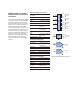
34959A breadboard module
Use this module to create your own custom
designs inside the 34980A mainframe.
You can control your custom circuits with
accesstoboththe+12Vand+5Vsup-
plies, 28 relay drive lines and two 8-bit
GPIO ports. Your design can be isolated
from the analog buses or connected by
loading the backplane switches. Simply
mount your custom PC board or other
components into the space provided and
connect via the two ribbon connectors
provided. The module is provided with two
50-or78-pinDsubconnectoropenings.For
custom connections, use the detachable
flat faceplates for easy modification. You
can program your circuitry using standard
read and write commands in SCPI.
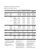
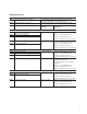
General specifications
Max module power dissipation 6 W
Power available
12Vregulationnoloadtofullload 10%
5Vregulationnoloadtofullload 5%
Max power from 12 V 6 W
Max power from 5 V 1 W
Relaydrives
Channels: 28, sink up to 100 mA
Max Input Voltage: 42 V
LeakageCurrent: 8uA
GPIO ports
Chan 1 and
Chan 2: 8 configure bits as input
or output
Chan 3: 3 output bits
High Input: 2 V min, 5.5 V max
LowInput: 0Vmin,0.8Vmax
HighOutput: 2.4V@4mA,3V@
500 uA
LowOutput: 0.4V@8mA
Available space for internal board/components:
5.4x7.5xeither0.9inchesheightwithoutPC
board,or0.7incheshighwithPCboard.
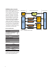
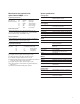
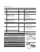
34959A Breadboard PC Board
Custom
Circuitry
and
Field
Wiring
Ribbon
Cable
Connector
(P101)
Ribbon
Cable
Connector
(P102)
34980A
Mainframe
Digital
Backplane
34980A
Analog
Buses
+5V
34980A Mainfram
eC
ustom PC Board
(Ch 911-914)
8 Bits
8 Bits
ABus Relay Drives
4
(Ch 002)
(Ch 001)
Digital I/O
Digital I/O
4 (2-Wire)
(Ch 101-128)
28
+12V
Relay Drives
4
Analog Bus
Relays (4)
(User Installed)
Figure 16. 34959A breadboard module