
User`s guide


19
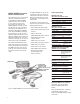
34950A 64-bit digital
I/O with memory and counter
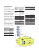
This module can be used to simulate or
detect digital patterns. It has eight 8-bit
digital I/O channels with handshaking, pat-
tern memory, two 10 MHz counters with
gate functions, and a programmable clock
output.
Digital input/output
The digital I/O bits are organized into
two banks of 32-bits. The I/O bits can be
configured and programmed as inputs or
outputs in 8-bit channels. The digital out-
puts can be configured as active drive or
opendrainoutputswitha10kΩpullup.
User supplied pull up resistors for up to 5
V outputs are also acceptable. The digital
inputs have programmable thresholds up to
5 V for compatibility with most digital logic
standards.
The onboard pattern memory can be used
to select and output digital stimulus or
bitstream patterns, or to capture external
digital data. Each bank has independent
memory and directional control so that one
bank can output data while the other
captures data. The memory can be divided
up to 64 Kbytes per 8-bit channel.
Specifically, the digital I/O channels also
have:
• Variableactivehighdriveoutputfrom
1.65 V to 5 V or open drain
• Variableinputthresholdsfrom
0 V to 5 V
• Configurablehandshaking
protocols including synchronous, and
strobe
• Programmablepolarity
• Sourceorsinkupto24mAwithaI
max
of
400 mA per module.
• Internalalarmingformaskable
pattern match
• 1hardwarepatterninterruptperbank
• Connectionsviastandard78-pinDsub
cables or detachable terminal block
Frequency counter/totalizer
The two channels can be used to
count
digital events, frequency, period,
duty cycle,
totalize, and pulse width. The counter/
totalizer also includes
• Programmablegatefunctionality
• Programmableinputthresholds
levels 0 V to 3 V
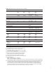
Digital input/output characteristics
Eight 8-bit channels:
8 bits wide, input or output, non-isolated
Vin 0V–5V
[1]
Vout 1.65V–5V
[1, 2]
Iout (max) 24 mA
[2]
Frequency (max) 10 MHz
[3]
I
Load
(max) 400 mA
t
rise
+t
fall
(typ) 6 ns
[5]
Handshake lines
Vin 0–5V
[4]
Vout 1.65–5V
[2, 4]
I out (max) 24 mA
[2]
Frequency (max) 10 MHz
Counter function characteristics
Maxfreq 10MHz(max)50%dutycycle
Vin 0V–5V
Min rise/fall time 5usec
Totalizer function characteristics
Maximumcount 2^32–1(4,294,967,296)
Max input freq 10 MHz (max),
rising or falling edge
programmable
Vin 0V–5V
Gateinput 0V–5V
Min rise/fall time 5usec
System clock generator characteristics
Frequency 20MHz–10Hzconfigurable
divide-by-n 24-bits,
programmable on/off
Vout 1.65V–5V
[2]
I out (max) 24 mA
[2]
Accuracy: 100 ppm
[1] Configurable by 8-bit channel
[2] Lowercurrentdriveatlowervoltages
[3] From memory with handshaking
[4] Configurable by bank
[5] 5 V, 50 pF load
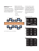
34980A system control modules
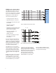
DIO
bank
1…8
Bank 1 Bank 2
Counter/
totalizer
1…8
Channel
101
8…%
8…%
8…%
8…%
32 Bits
Bit8
Bit15
Bit16
Bit23
Bit24
Bit31
Bit0
Bit7
Bit8
Bit15
Bit16
Bit23
Bit24
Bit31
Bit0
Bit7
INTR
Channel
301
Channel
102
Channel
103
Channel
104
H0
H1
H2
IN
Gate
IN
Gate
Counter/
totalizer
2…8
32 Bits
Channel
302
Clock
out
24 Bits
20 MHz – 10 Hz
CLK
DIO
bank
2…8
Channel
201
8…%
8…%
8…%
8…%
INTR
Channel
202
Channel
203
Channel
204
H0
H1
H2
Figure 13. 34950A 64-channel digital I/O