
User`s guide


13
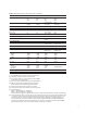
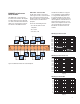
Table 4. Matrix selection table—specifications and characteristics
34931A 34932A 34933A 34934A
Channels/configurations dual 4x8 dual 4x16 dual 4x8 quad 4x32
8x8 8x16 8x8 4x128
4x16 4x32 4x16 8x64
quad 4x8, 1-wire 16x32
Switchtype Armature Armature Reed Reed
latching latching non-latching non-latching
Input characteristics (per channel)
Max volts ± 300 V
[1]
± 300 V
[1]
± 150 V peak
[2]
± 100 V peak
Maxcurrent(DC,ACRMS)
Switch current 1 A 1 A 0.5 A
[5]
/0.05 A
[8]
0.5 A
Carry current 2 A 2 A 1.5 A
[5]
/0.05 A
[8]
0.5 A
Power (W, VA)
[2, 6]
60 W 60 W 10 W
[7]
10 W
Volt-Hertz limit 10
8
10
8
10
8
10
8
Initial closed channel res
[3][9]
<1.5Ω <1.5Ω < 1.5 Ω
[5]
/200 Ω
[8]
<1Ω/100Ω
nominal
General Specifications
Offset voltage
[3]
< 3 uV < 3 uV < 50 uV < 20 uV
< 100 uV 1-wire < 50 uV 1-wire
DCIsolation(ch-ch,ch-earth) >10GΩ >10GΩ >10GΩ 10GΩ
AC characteristics
Bandwidthatterminalblock
[4]
30 MHz 30 MHz 30 MHz
[5]
/4 MHz
[8]
35 MHz 2-wire
2 MHz 1-wire 15 MHz 1-wire
Crosstalk at terminal block (ch-ch)
[4]
300kHz -65dB -65dB -65dB -65dB
1MHz -55dB -55dB -55dB -55dB
20MHz -30dB -30dB -40dB -33dB
Capacitance at terminal block
HI-LO 50pF 50pF 80pF 45pF
LO–earth 80pF 80pF 75pF 250pF
General characteristics
Relaylife,typical
Noload 100M 100M 1000M
10 V, 100 mA 10 M 10 M 10 M 1000 M operations
Ratedload 100k 100k 10k
Open/close time 4 ms/4 ms 4 ms/4 ms 0.5 ms/0.5 ms 0.35 ms/0.10 ms
Analogbusbackplaneconnection Bank2 Bank2 Bank2 No
[1] DCorACRMSvoltage,channel-to-channelorchannel-to-earth
[2] Peak voltage, channel-to-channel or channel-to-earth
[3] Into analog bus. System errors are included in the internal DMM
measurement accuracy specifications
[4] 50Ωsource,50Ωload,differentialmeasurementsverified(Sdd21)
[5] Withinputresistorsbypassed.Bypassingresistorswillreduce
lifetime of relays. See the rated load relay life characteristics.
[6] Limitedto6Wchannelresistancepowerlosspermodule
[7] Powerrestrictionsallowonly20channelstobeclosedatonetime
[8] ProtectionResistors:
34933A-100Ω±5%;0.5W;TC=±200ppm/°C.
34934A-100Ω±1%;0.25W;TC=±100ppm/°C.
If this resistance is not bypassed in the low side source line of a 4-wire resistance measurement, the 100 Ω range is limited.
[9] Channelresistanceistypically<1.5Ωbutcangoashighas50Ωwhenachannelisusedinmeasurementapplicationswith
< 10 mA load current. Increased relay channel resistance for measurements with load currents below 10 mA can occur on
cards that have been out of service or following relay inactivity for periods of greater than 1 week. Switching relays for
2K cycles prior to use may reduce the variation in channel resistance. Applies to the 34931A and 34932A. Agilent recom-
mends the use of 4-wire Ohms for resistance measurements. For high accuracy voltage measurements, select the DMM
inputresistancesettingof>10Gohmstominimizetheimpactofrelaycontactresistance.