
User`s guide

10
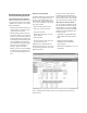
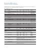
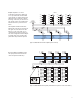
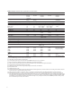
Table 3. Multiplexer selection table—specifications and characteristics
34921A 34922A 34923A 34924A 34925A
Channels/configurations 402-wire 702-wire 801-wire 702-wire 801-wire
20 4-wire 35 4-wire 40 2-wire 35 4-wire 40 2-wire
4-current 20 4-wire 20 4-wire
1.5 A Fused
Switch type
Armature
Armature Reed Reed Optically
latching
latching isolated FET
Input characteristics (per channel)
Max volts ± 300 V
[1]
± 300 V
[1]
± 150 V peak
[2]
± 150 V peak
[2]
± 80 V peak
[2]
Maxcurrent(DC,ACRMS)
Switch current 1 A 1 A 0.5 A
[5]
/ 0.05 A
[11]
0.5 A
[5]
/ 0.05 A
[11]
0.02 A
[8]
Carry current 2 A 2 A 1.5 A
[5]
/ 0.05 A
[11]
1.5 A
[5]
/ 0.05 A
[11]
Power (W, VA)
[6]
60 W 60 W 10 W 10 W 1.6 W
Volt-Hertz limit 10
8
10
8
10
8
10
8
10
7
Initial closed channel res
[3][12]
<1.5Ω <1.5Ω < 1.5 Ω
[5]
/200 Ω
[11]
< 1.5 Ω
[5]
/200 Ω
[11]
<700Ω
nominal nominal
General specifications
Offset voltage
[3]
< 3 uV < 3 uV < 50 uV < 50 uV < 3 uV
< 100 uV 1-wire
DCIsolation(ch-ch,ch-earth) >10GΩ >10GΩ >10GΩ >10GΩ >10GΩ
Leakagecurrent
[3]
N/A N/A N/A N/A 20nA
[9]
T/C cold junction accuracy
[3, 10]
<1°C N/A N/A N/A N/A
AC characteristics
Bandwidthatterminalblock
[4]
45 MHz 25 MHz 45 MHz
[5]
/4 MHz 25 MHz
[5]
/4 MHz
[11]
1 MHz
10 MHz 1-wire
Crosstalk at terminal block (ch-ch)
[4]
300kHz -75dB -75dB -75dB -75dB Notrecommendedfor
RFsignalswitching
1MHz -75dB -75dB -75dB -70dB
20MHz -50dB -50dB -50dB -45dB
45MHz -40dB -40dB
Capacitance at terminal block
HI-LO 150pF 250pF 130pF 200pF 100pF
LO–earth 150pF 200pF 120pF 170pF 300pF(600pF1-wire)
[1]
DCorACRMSvoltage,channel-to-channelorchannel-to-earth
[2] Peak voltage, channel-to-channel or channel-to-earth
[3] Into analog bus. System errors are included in the internal DMM measurement accuracy specifications
[4] 50Ωsource,50Ωload,differentialmeasurementsverifiedwith4-portnetworkanalyzer(Sdd21)
[5] Withinputresistorsbypassed.Bypassingresistorswillreducelifetimeofrelays.Seetheratedloadrelaylifecharacteristics.
[6] Limitedto6Wofchannelresistancepowerlosspermodule
[7] Speedsarefor2-wireohmsorDCV,4
1
/
2
digits, delay 0, display off, autozero off, and within bank
[8] DC or peak AC current
[9] Ambient temperature < 30°C
[10] Includes 0.5°C temperature reference sensor and 0.5°C terminal block isothermal gradient error, measured under worst case loading of the mainframe; see User’s
Guide for information on supported external reference sensors
[11]Withinputprotectionresistors:2x100Ω±5%;0.5W;TC=±200ppm/°C.Theseriesresistanceofthe34923/24/25limitstheuseofthe100Ωrange.
[12]Channelresistanceistypically<1.5Ωbutcangoashighas50Ωwhenachannelisusedinmeasurementapplicationswith<10mAloadcurrent.Increased
relay channel resistance for measurements with load currents below 10 mA can occur on cards that have been out of service or following relay inactivity for peri-
ods of greater than 1 week. Switching relays for 2K cycles prior to use may reduce the variation in channel resistance. Applies to the 34921A and 34922A. Agilent
recommendstheuseof4-wireOhmsforresistancemeasurements.Forhighaccuracyvoltagemeasurements,selecttheDMMinputresistancesettingof>10G
ohms to minimize the impact of relay contact resistance.