
Technical data


122 34980A Service Guide
5 Disassembly and Repair
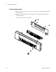
Backplane Removal
1 Remove the front panel (see the procedure on page 119) and the DMM
(see the procedure on page 121).
2 Use a 3/16” nut driver to remove the rear panel Analog Bus DB9
connector. Unclip the connector cable from the mainframe.
3 Remove the five T20 Torx screws holding the backplane assembly to the
chassis and lift the printed circuit assembly out.