
Technical data


Troubleshooting and Diagnostics 4
34980A Service Guide 107
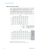
34933A Dual/Quad 4x8 Reed Matrix
Using program commands or the front panel of the 34980A, you can
configure the 34933A dual/quad 4x8 reed matrix module for differential
(2- wire) mode or single- ended (1- wire) mode.
The 34933A module contains 100
in- rush resistors that are used to
protect the reed relays from reactive loads. If you have applications where
in- rush resistors interfere with measurements, connections are provided
on the terminal blocks for you to bypass the in- rush resistors that are
located on the columns.
Two-Wire Mode
In 2- wire mode, the 34933A module contains two matrices, each with 32
2- wire crosspoint non- latching reed relays organized in a 4- row by
8- column configuration. Every row and column are made up of two wires
each, a high (H) and a low (L). Each crosspoint relay has a unique
channel number representing the row and column that intersect to create
the crosspoint. For example, channel 308 represents the crosspoint
connection between row 3 and column 08 (all columns consisting of two
digits; in this case the digits are 08). See the simplified schematic on
page 108.
One-Wire Mode
In 1- wire mode, the 34933A module contains four matrices (1 through 4),
each with 32 1- wire crosspoint non- latching reed relays organized in a
4- row by 8- column configuration. Every row and column has one wire
each. Each crosspoint relay has a unique channel number representing the
matrix, and the single- wire row and column that intersect to make the
crosspoint. For example, channel 218 represents Matrix 2, row 1 and
column 8. See the simplified schematic on page 109.