
Technical data


Troubleshooting and Diagnostics 4
34980A Service Guide 93
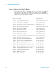
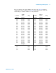
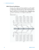
For the 34921A, relay and fuse part numbers are given on page 126 and
the component locator is shown on page 136. The table below shows the
relationship of channel numbers to relay numbers.
*The current switches use two relays to create a “make-before-break” circuit. You should replace both relays.
Bank 1 Bank 2
Channel Relay Channel Relay
001 K601 021 K721
002 K602 022 K722
003 K603 023 K723
004 K604 024 K724
005 K605 025 K725
006 K606 026 K726
007 K607 027 K727
008 K608 028 K728
009 K609 029 K729
010 K610 030 K730
011 K611 031 K731
012 K612 032 K732
013 K613 033 K733
014 K614 034 K734
015 K615 035 K735
016 K616 036 K736
017 K617 037 K737
018 K618 038 K738
019 K619 039 K739
020 K620 040 K740
Backplane Backplane
911 K911 921 K921
912 K912 922 K922
913 K913 923 K923
914 K914 924 K924
Current* Current*
041 K841, K841S,
F1041
043 K843, K843S,
F1043
042 K842, K842S,
F1042
044 K844, K844S,
F1044
Current Backplane
931 K931