Agilent 34937A-34939A General Purpose Switch Modules User’s Guide Agilent Technologies, Inc.
Notices © Agilent Technologies, Inc. 2008 Warranty No part of this manual may be reproduced in any form or by any means (including electronic storage and retrieval or translation into a foreign language) without prior agreement and written consent from Agilent Technologies, Inc. as governed by United States and international copyright laws. Microsoft® and Windows® are U.S. registered trademarks of Microsoft Corporation.
Additional Safety Notices The following general safety precautions must be observed during all phases of operation of this instrument. Failure to comply with these precautions or with specific warnings or instructions elsewhere in this manual violates safety standards of design, manufacture, and intended use of the instrument. Agilent Technologies assumes no liability of the customer’s failure to comply with the requirements. General Do not use this products in any manner not specified by the manufacturer.
The Declaration of Conformity (DoC) for the 34980A mainframe instrument can be found on page iii in the 34980A Mainframe User’s Guide. That DoC applies to the 34980A mainframe and all available plug- in modules.
Contents General Purpose Switch Modules . . . . . . . . . . . . . . . . . . . . . . . . . . . . . . . . . . . . . . . . . . . . . .1 Operating Considerations. . . . . . . . . . . . . . . . . . . . . . . . . . . . . . . . . . . . . . . . . . . . . . . . . . . . . .2 Electrical Considerations . . . . . . . . . . . . . . . . . . . . . . . . . . . . . . . . . . . . . . . . . . . . . . . . . . .2 Temperature Sensor. . . . . . . . . . . . . . . . . . . . . . . . . . . . . . . . . . . . . . . . . . . . . . . . . .
vi Agilent 34937A-34939A General Purpose Switch Modules User’s Guide
General Purpose Switch Modules General Purpose Switch Modules This User’s Guide covers the following two plug- in modules for the Agilent 34980A Multifunction Switch/Measure Unit: 34937A 34938A 34939A 28-channel Form C and 4-channel Form A 28-channel 5-amp Form A 64-Channel High-Density Form A • The 34937A provides independent control of 32 relays, including: • Twenty- eight Form C relays, each rated for 1 A at 60 W per channel • Four Form A (SPST) relays, each rated for 5 A at 150 W per channel.
Operating Considerations. Operating Considerations. WA R N I N G Do not connect either the 34937A, 34938A or 34939A module directly to a mains power outlet. If it is necessary to switch a mains voltage or any circuit where a large inductive load may be switched, you must add signal conditioning elements to reduce the potential transients before they reach the module or the Analog Buses.
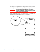
Operating Considerations. The jumpers are positionable across pins 1–2 (“Open” position) or across pins 2–3 (“Maintain” position). When shipped from the factory, the power- fail jumper is in the Maintain position (i.e. all relays maintain their present state when power fails). Before changing the position of the jumper, remove external WA R N I N G connections from the module. Wait five to ten seconds to allow the module’s internal capacitors to discharge.
34937A, 34938A and 34939A SCPI Programming Examples 34937A, 34938A and 34939A SCPI Programming Examples The programming examples below provide you with SCPI command examples to use for actions specific to the general purpose switch modules. The slot and channel addressing scheme used in these examples follow the form sccc where s is the mainframe slot number (1 through 8) and ccc is the channel number.
34937A, 34938A and 34939A SCPI Programming Examples Reading Cycle Count and Resetting Modules to Power-On State Example: Reading the cycle count for a relay (all switch modules) The following command returns the relay cycle count on channel 7 and channel 16 for a module in slot 1. DIAGnostic:RELay:CYCLes? (@1007,1016) Example: Clearing the cycle count for a relay (all switch modules) The following command resets the relay cycle count on channels 7 and 16 for a module in slot 1.
34937A 32-Channel GP Switch Module 34937A 32-Channel GP Switch Module The 34937A general- purpose switch module provides independent control of: • Twenty- eight Form C (SPDT) latching relays rated at 1 A • Four Form A (SPST) latching relays rated at 5 A. You can set the power- failure state for these 5 A relays (see “Hardware Power- Fail Jumper” on page 2).
34937A 32-Channel GP Switch Module 34937A D-Sub Connectors Bank 1 Bank 1 For orientation, the D-sub connector end of the module is facing you.
34937A 32-Channel GP Switch Module 34937T Terminal Block This terminal block with screw- type connections is labeled with the model number and the abbreviated module name. In addition, space is available on the label for you to write the slot number. The 34980A Product Reference CD (shipped with the instrument) contains a 34937T Wiring Log for you to document your wiring configuration for this module. You can open the wiring log file in Microsoft® Excel® or Adobe® Acrobat® format.
34938A 20-Channel High-Current GP Switch Module 34938A 20-Channel High-Current GP Switch Module The 34938A high- current GP switch module provides twenty 5 A Form A (SPST) relays for general purpose switching needs. You can set the power- failure state for these 5 A relays (see “Hardware Power- Fail Jumper” on page 2). NOTE A temperature sensor on these modules triggers system interrupts when high-carry current-induced heat on the modules reaches a threshold of 70 oC.
34938A 20-Channel High-Current GP Switch Module 34938A D-Sub Connectors Bank 1 Bank 1 Bank 2 For orientation, the D-sub connector end of the module is facing you.
34938A 20-Channel High-Current GP Switch Module 34938T Terminal Block This terminal block with screw- type connections is labeled with the model number and the abbreviated module name. In addition, space is available on the label for you to write the slot number. The 34980A Product Reference CD (shipped with the instrument) contains a 34938T Wiring Log for you to document your wiring configuration for this module. You can open the wiring log file in Microsoft® Excel® or Adobe® Acrobat® format.
34939A 64-Channel High-Density Form-A GP Switch Module 34939A 64-Channel High-Density Form-A GP Switch Module The 34939A high- density GP switch module provides sixty- four 1 A Form A (SPST) relays for general purpose switching needs. You can set the power- failure state for these relays (see “Hardware Power- Fail Jumper” on page 2). NOTE A temperature sensor on these modules triggers system interrupts when high-carry current-induced heat on the modules reaches a threshold of 70 oC.
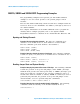
34939A 64-Channel High-Density Form-A GP Switch Module 34939A D-Sub Connectors Bank 1 Bank 1 4C 4NO 1 7C 2 For orientation, the D-sub connector end of the module is facing you.
34939A 64-Channel High-Density Form-A GP Switch Module Bank 2 Bank 1 Bank 2 For orientation, the D-sub connector end of the module is facing you.
34939A 64-Channel High-Density Form-A GP Switch Module 34939T Terminal Block This terminal block with screw- type connections is labeled with the model number and the abbreviated module name. In addition, space is available on the label for you to write the slot number. The 34980A Product Reference CD (shipped with the instrument) contains a 34939T Wiring Log for you to document your wiring configuration for this module. You can open the wiring log file in Microsoft® Excel® or Adobe® Acrobat® format.
34939A 64-Channel High-Density Form-A GP Switch Module 16 Agilent 34937A-34939A General Purpose Switch Modules User’s Guide
Index Index Numerics W 34929A pinouts, 13 34937A connector pinouts, 7 description, 1, 6 simplified schematic, 6 snubber circuitry, 8 terminal block, 8 wiring log, 8 34938A connector pinouts, 10 description, 1, 9 simplified schematic, 9 snubber circuitry, 11 terminal block, 11 wiring log, 11 34939A connector pinouts, 13 description, 1, 12 simplified schematic, 12 terminal block, 15 wiring log, 15 warranty, ii C connector pinouts 34937A, 7 34938A, 10 34939A, 13 D D-sub pinouts 34937A, 7 34938A, 10 34939
Index 18 Agilent 34937A-34939A General Purpose Switch Modules User’s Guide