
Programming instructions

84 Appendix A Specifications
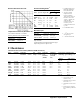
2 Accuracy
1
(ppm of Reading + ppm of Range)
Two-Wire Ohms Accuracy
For Two-Wire Ohms ( OHM ) accuracy, add the following offset errors to the Four-Wire Ohms ( OHMF )
accuracy. 24 Hour: 50 mΩ. 90 Day: 150 mΩ. 1 Year: 250 mΩ. 2 Year: 500 mΩ
Additional Errors
Range
24 Hour
2
90 Day
3
1 Year
3
2 Year
3
10 Ω 5+3 15+5 15+5 20+10
100 Ω 3+3 10+5 12+5 20+10
1 kΩ 2+0.2 8+0.5 10+0.5 15+1
10 kΩ 2+0.2 8+0.5 10+0.5 15+1
100 kΩ 2+0.2 8+0.5 10+0.5 15+1
1 MΩ 10+1 12+2 15+2 20+4
10 MΩ 50+5 50+10 50+10 75+10
100 MΩ 500+10 500+10 500+10 0.1%+10
1 GΩ 0.5%+10 0.5%+10 0.5%+10 1%+10
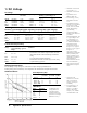
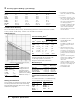
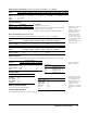
*RMS Noise
Range Multiplier
10 Ω & 100 Ω ×10
1k Ω to 100 kΩ ×1
1 MΩ ×1.5
10 MΩ ×2
100 MΩ ×120
1 GΩ ×1200
1. Specifications are for PRESET;
NPLC 100; OCOMP ON; OHMF.
2. Tcal ± 1°C.
3. Specifications for 90 day, 1 year
,
and 2 year are within 24 hours and
± 1°C of last ACAL; Tcal ±5°C.
Add 3 ppm of reading additional
error for Keysight factory
traceability of 10 KΩ to US NIST.
Traceability is the absolute error
relative to National Standards
associated wifh the source of last
external calibration.
4. For PRESET; DELAY 0; DISP
OFF; OFORMAT DINT;
ARANGE OFF.
For OHMF or OCOMP ON, the
maximum reading rates will be
slower.
5. Ohms measurements at rates <
NPLC 1 are subject to
potential
noise pickup. Care must be taken
to
provide adequate shielding and
guarding to maintain measurement
accuracies.
6.
Aperture is selected independent
of line frequency (LFREQ). These
apertur
es are for 60 Hz NPLC
values where
1 NPLC=1/ LFREQ. For 50 Hz
and
NPLC indicated, aperture will
increase by 1.2 and reading rates
will decrease by 0.833.
7. For OFORMAT SINT
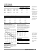
Selected Reading Rates
4
Measurement Consideration
Keysight recommends the use of PTFE cable
or other high impedance, low dielectric
absorption cable for these measurements.
Maximum Input
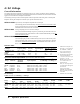
Temperature Coefficient (Auto-Zero
off)
For a stable environment ± 1°C add the following
error for AZERO OFF. (ppm of Range) /°C
Readings/Sec
NPLC
5
Aperture Digits
Auto-Zero
Off
Auto-Zero
On
0.0001 1.4 µs 4.5
100,000
7
4,130
0.0006 10 µs 5.5 50,000 3,150
0.01 167 µs
6
6.5 5,300 930
0.1 1.66 ms
6
6.5 592 245
1 16.6 ms
6
7.5 60 29.4
10 0.166 s
6
7.5 6 3
100 7.5 36 /min 18/min
Rated
Input
Non-
Destructive
HI to LO ± 1000 V pk ± 1000 V pk
HI & LO Sense to LO ± 200 V pk ± 350 V pk
LO to Guard ± 200 V pk ± 350 V pk
Guard to Earth ± 500 V pk ± 1000 V pk
Range Error Range Error
10 Ω 50 1 MΩ 1
100 Ω 50 10 MΩ 1
1 kΩ 5 100 MΩ 10
10 kΩ 5 1 GΩ 100
100 kΩ 1
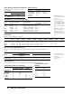
Settling Characteristics
For first reading error following range change, add the
total 90 day measurement error for the current range.
Preprogrammed settling delay times are for < 200 pF
external circuit capacitance.
For RMS noise error,
multiply RMS noise
result from graph by
multiplier in chart. For
peak noise error, multiply
RMS noise error by 3.