
Technical data

Performance Tests and Calibration 1
Adjustments
34450A Service Guide 37
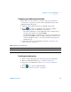
6 When the calibration has been completed for the selected range, the
status box shows DONE, and the value in the Calibration Range box
flashes.
7 Verify the Ohms gain adjustments using the “Ohms gain verification
test” on page 14.
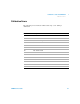
Table 1-15 Ohms gain adjustment
Input Function Range
0 Ω
[1]
2-W Resistance/4-W Resistance Any
20
Ω, 70 Ω, 100 Ω 100 Ω
0.2 kΩ, 0.7 kΩ, 1 kΩ 1k Ω
2 kΩ, 7 kΩ, 10 kΩ 10 kΩ
20 kΩ, 70 kΩ, 100 kΩ 100 kΩ
0.2 MΩ, 0.7 MΩ, 1 MΩ 1 MΩ
2 MΩ, 7 MΩ, 10M Ω 10 MΩ
100 MΩ 100 MΩ
Input terminal open
[2]
2-W Resistance(only) 100 MΩ
Do not remove test lead
[3]
2-W Resistance(only) 100 MΩ
[1] Configure to 2-wire compensation mode for calibrator for better accuracy. Cal item 0 Ω only calibrated once during ohms
gain adjustment procedure. You need to re-calibrate once you exit calibration mode.
[2] Remove test lead for 2-wire calibration.
[3] Do not remove kelvin 4-wire connection at the other end of the test leads (for DUT measurement) for 4-W resistance
calibration.
NOTE
Before initiating any gain adjustment procedures, perform the zero adjustment at any range
first.