
Technical data

1 Performance Tests and Calibration
Adjustments
36 34450A Service Guide
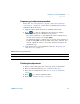
Ohms gain adjustment procedure
Review the “Test Considerations” on page 5 and “Gain adjustment
considerations” on page 29 sections before performing this procedure.
This procedure applies to both 2- W Resistance and 4- W Resistance
calibration mode.
Calibration Mode: 2- W Resistance/4- W Resistance
1 Press or to select the calibration range.
2 The Measurement box displays the uncalibrated value and the
Calibration Point box displays the reference value.
3 Apply the input signal shown in the Calibration Point Box.
4 Press to start the adjustment. The Status box displays
CALIBRATING indicates the calibration is in progress.
• Successful completion of each adjustment value is indicated by a
message in the Status box showing PASS.
• An adjustment failure is indicated by a message in the Status box
briefly showing FAIL. Check the input value, range, function, and
entered adjustment value to correct the problem and repeat the
adjustment step.
5 Repeat step 1 through 4 for each gain adjustment point shown in the
preset calibration point box.
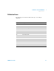
Caution: Connect calibrator to multimeter’s 10 A and LO terminals before applying 1A and 10 A range.
0.1 A, 0.7 A, 1 A 1 kHz 1 A
1 A, 7 A, 10 A 1 kHz 10 A
Table 1-14 AC current gain adjustment
Input Instrument Settings
Current, rms Frequency Function Range