
Technical data

Performance Tests and Calibration 1
Adjustments
34450A Service Guide 31
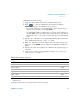
Calibration mode: DC voltage
1 Apply the input signal shown in the Calibration Point box.
2 Press to start the adjustment. The Status box displays
CALIBRATING indicates the calibration is in progress.
• Successful completion of each adjustment value is indicated by a
message in the Status box showing PASS.
• An adjustment failure is indicated by a message in the Status box
showing FAIL. Check the input value, range, function, and entered
adjustment value to correct the problem and repeat the adjustment
step.
3 Repeat steps 1 through 2 for each gain adjustment point shown in the
preset Calibration Point box , Table 1- 11 below.
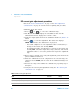
4 When the calibration has been completed for the selected range, the
status box shows DONE, and the value in the Calibration Range box
flashes.
5 Increase the range and continue the calibration by repeating steps 1
through 4.
6 Verify the DC voltage gain adjustments using the “DC voltage gain
verification test” on page 11.
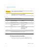
Table 1-11 DC voltage gain adjustment
Input Function Range
0 mV
[1]
DC voltage 1 V
0.2 V, 0.4 V, 0.6 V, 0.8 V, 1 V, 1.2 V, –0.2 V, –0.4 V, –0.6 V, –0.8 V, –1V, –1.2 V
[2]
1 V
100 mV, –100 mV 100 mV
10 V, –10 V 10 V
100 V, –100 V 100 V
1000 V, –1000 V 1000 V
Caution: Set the calibrator output to 0 V before disconnecting from the multimeter input terminals.
[1] Cal Item 0 mV only calibrated once during DC voltage gain adjustment procedure. You need to re-calibrate once you exit
calibration mode.
[2] Calibration need to be done on 1 V range first before proceeds to other ranges.