
Technical data

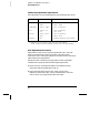


Valid Gain Adjustment Input Values
Gain adjustment can be accomplished using the following input values.
Gain Adjustment Procedure
Adjustment for each function should be performed only in the order
shown in the performance verification table. See “Performance
Verification Tests,” starting on page 65, for the performance verification
tables used for gain adjustments.
Review the “Test Considerations” (page 64) and “Gain Adjustment
Considerations” (page 79) sections before beginning this test.
1 Select a function to be adjusted. Refer to the appropriate gain
verification table (see pages 69 through 71).
2 Apply the input signal shown in the “Input” column of the
appropriate verification table. Always complete tests in the same
order as shown in the appropriate verification table.
Function Range Valid Calibration Input Values
DC V
Ω 2W, Ω 4W
DC I
AC V [1]
Frequency
100 mV to 100 V
1000 V
100
Ω to 10 MΩ
10 mA to 1 A
3 A
10 mV to 100 V
750 V
Any
0.9 to 1.1 x Full Scale
900 V to 1050 V
0.9 to 1.1 x Full Scale
0.9 to 1.1 x Full Scale
1 A to 3.03 A
0.9 to 1.1 x Full Scale
195 V to 770 V
Any Input > 100 mV rms, 1 kHz
– 100 kHz
[1] Valid frequencies are as follows: 1 kHz
±10% for the 1 kHz calibration,
45 kHz – 100 kHz for the 50 kHz calibration, and 10 Hz
±10% for the 10 Hz calibration.
Chapter 4 Calibration Procedures
Gain Adjustment
80