
Technical data


Pass/Fail Output
(continued)
Installation Procedure
The assembly drawings and schematics are located in chapter 9,
“Schematics.”
1 Unscrew the two rear bezel captive screws (see the mechanical
disassembly drawing on page 9-3).
2 Remove one screw from bottom cover (see the mechanical
disassembly drawing on page 9-3).
3 Slide the metal cover off of the chassis (see the mechanical
disassembly drawing on page 9-3).
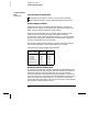
4 Install
JM710 and JM711 located adjacent to the power supply
connector,
P751. A bare wire may be used if a 0 ohm surface
mount resistor is not available. (See the component locator
diagram for the 34401-66501 Main PC Board on page 9-5.)
5 Reassemble the multimeter. Make sure to reinstall the bottom
cover screw.
Do not use the RS-232 interface if you have configured the multimeter
to output pass/fail signals on pins 1 and 9. Internal components on the
interface circuitry may be damaged.
Chapter 6 Service
To Connect the Pass/Fail Output Signals
116