
Technical data

DC Amplifier
The DC Amplifier circuit (schematic shown on page 9-10) is used by
every measuring function except frequency and period. Analog switch
U101B selects various input signals for measurement by the ADC.
Switch
U101B has three sources which can be dynamically selected:
measure customer input (
MC), measure zero input (MZ), and precharge
(
PRE). The MC state is the actual input measurement. The MZ state
measures internal offset voltages which are also present in the
MC
measurement. The final measurement result is computed from MC–MZ.
The
PRE state is used to “precharge” internal capacitances to reduce
charge injection to the input terminal from the dynamic switching of
MC
and MZ. Autozero off disables the dynamic switching of the amplifier
input. However, a new
MZ value is automatically taken whenever a new
function or range is selected, even if autozero is turned off. [1]
In the dc voltage function, ranging is accomplished through both input
relay switching (
K101–K104) and solid state switching (U101). As a
result, the input to the
ADC has the same nominal 10V value for a full
scale input on each range. The dc input op amp is comprised of source
follower dual
FET U104, amplifier U106, and associated bias circuitry.
The feedback resistors
U102C and switches U101C select non-inverting
amplifier gains of x1, x10, and x100 for the dc input amplifier circuit.
Amplifier output
ADIN drives the dc input to the a-to-d converter for all
measuring functions.
[1] The output of the input amplifier will continue to cycle from a 0 V (MZ) level
to the MC amplified input level during autozero operation. Autozero can be
disabled from the remote interface or suspended using the TRIGGER
SINGLE configuration from the front panel.
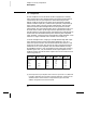
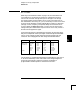
DCV Range U102A Divider U101 Input Amplifier Gain ADC Input
100 mV
1 V
10 V
100 V
1000 V
1/100
1/100
Pin 5
Pin 5
Pin 5
Pin 8
Pin 8
x100
x10
x1
x10
x1
10 V
10 V
10 V
10 V
10 V
Chapter 5 Theory of Operation
DC Amplifier
96