Agilent 34401A 6 ½ Digit Multimeter Service Guide Agilent Technologies
Notices © Agilent Technologies, Inc. 1991 - 2007 Warranty No part of this manual may be reproduced in any form or by any means (including electronic storage and retrieval or translation into a foreign language) without prior agreement and written consent from Agilent Technologies, Inc. as governed by United States and international copyright laws. The material contained in this document is provided “as is,” and is subject to being changed, without notice, in future editions.
Safety Information General Do not use this product in any manner not specified by the manufacturer. The protective features of this product may be impaired if it is used in a manner not specified in the operation instructions. Do not install substitute parts or perform any unauthorized modification to the product. Return the product to an Agilent Technologies Sales and Service Office for service and repair to ensure that safety features are maintained.
LO to Ground Protection Limit. The LO input terminal can safely "float" a maximum of 500 Vpk relative to ground. WARN IN G IEC Measurement Category II. The HI and LO input terminals may be connected to mains in IEC Category II installations for line voltages up to 300 VAC. To avoid the danger of electric shock, do not connect the inputs to mains for line voltages above 300 VAC. See "IEC Measurement Category II Overvoltage Protection" on the following page for further information.
IEC Measurement Category II includes electrical devices connected to mains at an outlet on a branch circuit. Such devices include most small appliances, test equipment, and other devices that plug into a branch outlet or socket. The 34401A may be used to make measurements with the HI and LO inputs connected to mains in such devices, or to the branch outlet itself (up to 300 VAC).
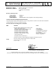
DECLARATION OF CONFORMITY According to ISO/IEC Guide 22 and CEN/CENELEC EN 45014 Manufacturer’s Name: Manufacturer’s Address: Agilent Technologies, Incorporated th 815 – 14 St. SW Loveland, Colorado 80537 USA Declares, that the product Product Name: Model Number: Product Options: Multimeter 34401A This declaration covers all options of the above product(s).
Note: Unless otherwise indicated, this manual applies to all serial numbers. The Agilent Technologies 34401A is a 61⁄2-digit, high-performance digital multimeter. Its combination of bench-top and system features makes this multimeter a versatile solution for your measurement needs now and in the future.
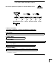
The Front Panel at a Glance 1 2 3 4 2 Measurement Function keys Math Operation keys Single Trigger / Autotrigger / Reading Hold key Shift / Local key 5 Front / Rear Input Terminal Switch 6 Range / Number of Digits Displayed keys 7 Menu Operation keys
The Front-Panel Menu at a Glance The menu is organized in a top-down tree structure with three levels.
Display Annunciators ∗ Adrs Rmt Man Trig Hold Mem Ratio Math ERROR Rear Shift 4W Turns on during a measurement. Multimeter is addressed to listen or talk over the GPIB interface. Multimeter is in remote mode (remote interface). Multimeter is using manual ranging (autorange is disabled). Multimeter is waiting for a single trigger or external trigger. Reading Hold is enabled. Turns on when reading memory is enabled. Multimeter is in dcv:dcv ratio function.
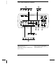
The Rear Panel at a Glance 1 2 3 4 Chassis Ground Power-Line Fuse-Holder Assembly Power-Line Voltage Setting Front and Rear Current Input Fuse 5 6 7 8 Voltmeter Complete Output Terminal External Trigger Input Terminal GPIB (IEEE-488) Interface connector RS-232 interface connector Use the front-panel Input / Output Menu to: • • • Select the GPIB or RS-232 interface (see chapter 4 in the “User’s Guide”). Set the GPIB bus address (see chapter 4 in the “User’s Guide”).
In This Book Specifications Chapter 1 lists the multimeter’s specifications and describes how to interpret these specifications. Quick Start Chapter 2 prepares the multimeter for use and helps you get familiar with a few of its front-panel features. Menu Tutorial Chapter 3 introduces you to the front-panel menu and steps you through several simple menu examples. Calibration Procedures Chapter 4 provides a detailed description of the multimeter’s calibrations and adjustments.
Contents Chapter 1 Specifications DC Characteristics 12 AC Characteristics 14 Frequency and Period Characteristics 16 General Information 18 Product Dimensions 19 To Calculate Total Measurement Error 20 Interpreting Multimeter Specifications 22 Configuring for Highest Accuracy Measurements 25 Chapter 2 Quick Start Contents To Prepare the Multimeter for Use 29 If the Multimeter Does Not Turn On 30 To Adjust the Carrying Handle 32 To Measure Voltage 33 To Measure Resistance 33 To Measure Current 34 To Meas
Contents Contents Chapter 4 Calibration Procedures Agilent Calibration Services 61 Calibration Interval 61 Time Required for Calibration 61 Automating Calibration Procedures 62 Recommended Test Equipment 63 Test Considerations 64 Performance Verification Tests 65 Zero Offset Verification 67 Gain Verification 69 Optional AC Performance Verification Tests 72 Calibration Security Code 73 Calibration Count 75 Calibration Message 75 Calibration Procedures 76 Aborting a Calibration in Progress 76 Zero Adjustmen
Contents Chapter 6 Service Operating Checklist 111 Types of Service Available 112 Repackaging for Shipment 113 Electrostatic Discharge (ESD) Precautions 114 Surface Mount Repair 114 To Replace the Power-Line Fuse 114 To Replace The Current Input Fuses 115 To Connect Pass/Fail Output Signals 115 Troubleshooting Hints 117 Self-Test Procedures 120 Chapter 7 Replaceable Parts Chapter 8 Backdating Contents To Order Replaceable Parts 126 Backdating and Part Changes 126 Replaceable Parts: 34401-66501 (Main Ass
10 Contents
1 1 Specifications
Chapter 1 Specifications DC Characteristics DC Characteristics Accuracy Specifications ± ( % of reading + % of range ) Test Current or Burden Voltage [1] 24 Hour [ 2 ] 23°C ± 1°C 90 Day 23°C ± 5°C 1 Year 23°C ± 5°C Temperature Coefficient /°C 0°C – 18°C 28°C – 55°C 0.0030 + 0.0030 0.0020 + 0.0006 0.0015 + 0.0004 0.0020 + 0.0006 0.0020 + 0.0006 0.0040 + 0.0035 0.0030 + 0.0007 0.0020 + 0.0005 0.0035 + 0.0006 0.0035 + 0.0010 0.0050 + 0.0035 0.0040 + 0.0007 0.0035 + 0.0005 0.0045 + 0.0006 0.0045 + 0.
Chapter 1 Specifications DC Characteristics 1 Operating Characteristics Measuring Characteristics DC Voltage Measurement Method: A/D Linearity: Input Resistance: 0.1 V, 1 V, 10 V ranges 100 V, 1000 V ranges Input Bias Current: Input Terminals: Input Protection: Resistance Measurement Method: Max.
Chapter 1 Specifications AC Characteristics AC Characteristics Accuracy Specifications Function True RMS AC Voltage [4] True RMS AC Current [4] ± ( % of reading + % of range ) [ 1 ] Frequency 24 Hour [ 2 ] 23°C ± 1°C 90 Day 23°C ± 5°C 1 Year 23°C ± 5°C Temperature Coefficient/°C 0°C – 18°C 28°C – 55°C 100.0000 mV 3 Hz – 5 Hz 5 Hz – 10 Hz 10 Hz – 20 kHz 20 kHz – 50 kHz 50 kHz – 100 kHz 100 kHz – 300 kHz [6] 1.00 + 0.03 0.35 + 0.03 0.04 + 0.03 0.10 + 0.05 0.55 + 0.08 4.00 + 0.50 1.00 + 0.04 0.
Chapter 1 Specifications AC Characteristics 1 Measuring Characteristics Operating Characteristics Measurement Noise Rejection [ 8 ] 70 dB AC CMRR Function ACV, ACI True RMS AC Voltage Measurement Method: Crest Factor: AC Filter Bandwidth: Slow Medium Fast Input Impedance: Input Protection: True RMS AC Current Measurement Method: Shunt Resistor: Burden Voltage: Input Protection: AC-coupled True RMS – measures the ac component of input with up to 400 Vdc of bias on any range.
Chapter 1 Specifications Frequency and Period Characteristics Frequency and Period Characteristics Accuracy Function Range [ 3 ] Frequency Frequency, Period [ 4 ] 100 mV to 750 V 3 Hz – 5 Hz 5 Hz – 10 Hz 10 Hz – 40 Hz 40 Hz – 300 kHz 24 Hour [ 2 ] 23°C ± 1°C 0.10 0.05 0.03 0.006 Specifications ± ( % of reading ) [ 1 ] 90 Day 23°C ± 5°C 0.10 0.05 0.03 0.01 1 Year 23°C ± 5°C 0.10 0.05 0.03 0.01 Temperature Coefficient/°C 0°C – 18°C 28°C – 55°C 0.005 0.005 0.001 0.
Chapter 1 Specifications Frequency and Period Characteristics 1 Measuring Characteristics Operating Characteristics Frequency and Period Measurement Method: Function Frequency, Period Voltage Ranges: Gate Time: Reciprocal-counting technique. AC-coupled input using the ac voltage measurement function. 100 mV rms full scale to 750 V rms. Auto or manual ranging.
Chapter 1 Specifications General Information General Information General Specifications Power Supply: Power Line Frequency: Power Consumption: Operating Environment: Storage Environment: Rack Dimensions (HxWxD): Weight: Safety: EMI: Vibration and Shock: Warranty: 100 V / 120 V / 220 V / 240 V ± 10%. 45 Hz to 66 Hz and 360 Hz to 440 Hz. Automatically sensed at power-on. 25 VA peak ( 10 W average ) Full accuracy for 0°C to 55°C Full accuracy to 80% R.H. at 40°C -40°C to 70°C 88.5 mm x 212.6 mm x 348.3 mm 3.
Chapter 1 Specifications Product Dimensions 1 Product Dimensions 103.8 mm 379.4 mm 261.1 mm 88. 5 mm 212. 6 mm 348. 3 mm TOP All dimensions are shown in millimeters.
Chapter 1 Specifications To Calculate Total Measurement Error To Calculate Total Measurement Error Each specification includes correction factors which account for errors present due to operational limitations of the multimeter. This section explains these errors and shows how to apply them to your measurements. Refer to “Interpreting Multimeter Specifications,” starting on page 22, to get a better understanding of the terminology used and to help you interpret the multimeter’s specifications.
Chapter 1 Specifications To Calculate Total Measurement Error 1 Understanding the “ % of range ” Error The range error compensates for inaccuracies that result from the function and range you select. The range error contributes a constant error, expressed as a percent of range, independent of the input signal level. The following table shows the range error applied to the multimeter’s 24-hour dc voltage specification. Range Input Level 10 Vdc 10 Vdc 10 Vdc 10 Vdc 1 Vdc 0.
Chapter 1 Specifications Interpreting Multimeter Specifications Interpreting Multimeter Specifications This section is provided to give you a better understanding of the terminology used and will help you interpret the multimeter’s specifications. Number of Digits and Overrange The “number of digits” specification is the most fundamental, and sometimes, the most confusing characteristic of a multimeter. The number of digits is equal to the maximum number of “9’s” the multimeter can measure or display.
Chapter 1 Specifications Interpreting Multimeter Specifications 1 Resolution Resolution is the numeric ratio of the maximum displayed value divided by the minimum displayed value on a selected range. Resolution is often expressed in percent, parts-per-million (ppm), counts, or bits. For example, a 61⁄2-digit multimeter with 20% overrange capability can display a measurement with up to 1,200,000 counts of resolution. This corresponds to about 0.0001% (1 ppm) of full scale, or 21 bits including the sign bit.
Chapter 1 Specifications Interpreting Multimeter Specifications Transfer Accuracy Transfer accuracy refers to the error introduced by the multimeter due to noise and short-term drift. This error becomes apparent when comparing two nearly-equal signals for the purpose of “transferring” the known accuracy of one device to the other.
Chapter 1 Specifications Configuring for Highest Accuracy Measurements 1 Configuring for Highest Accuracy Measurements The measurement configurations shown below assume that the multimeter is in its power-on or reset state. It is also assumed that manual ranging is enabled to ensure proper full scale range selection. DC Voltage, DC Current, and Resistance Measurements: • Set the resolution to 6 digits (you can use the 6 digits slow mode for further noise reduction).
26
2 2 Quick Start
Quick Start One of the first things you will want to do with your multimeter is to become acquainted with its front panel. We have written the exercises in this chapter to prepare the multimeter for use and help you get familiar with some of its front-panel operations. The front panel has two rows of keys to select various functions and operations. Most keys have a shifted function printed in blue above the key. To perform a shifted function, press Shift (the Shift annunciator will turn on).
Chapter 2 Quick Start To Prepare the Multimeter for Use To Prepare the Multimeter for Use The following steps help you verify that the multimeter is ready for use. 1 Check the list of supplied items. Verify that you have received the following items with your multimeter. If anything is missing, contact your nearest Agilent Sales Office. One test lead kit. One power cord. This Service Guide. One User’s Guide. One folded Quick Reference card. Certificate of Calibration.
Chapter 2 Quick Start If the Multimeter Does Not Turn On If the Multimeter Does Not Turn On Use the following steps to help solve problems you might encounter when turning on the multimeter. If you need more help, see chapter 6 for instructions on returning the multimeter to Agilent for service. 1 Verify that there is ac power to the multimeter. First, verify that the multimeter’s Power switch is in the “On” position.
Chapter 2 Quick Start If the Multimeter Does Not Turn On 1 Remove the power cord. Remove the fuse-holder assembly from the rear panel. 2 Remove the line-voltage selector from the assembly. 2 See rear panel for proper fuse rating. Agilent Part Number: 2110-0817 (250 mAT) 3 Rotate the line-voltage selector until the correct voltage appears in the window. 4 Replace the fuse-holder assembly in the rear panel.
Chapter 2 Quick Start To Adjust the Carrying Handle To Adjust the Carrying Handle To adjust the position, grasp the handle by the sides and pull outward. Then, rotate the handle to the desired position.
Chapter 2 Quick Start To Measure Voltage To Measure Voltage 2 Ranges: 100 mV, 1 V, 10 V, 100 V, 1000 V (750 Vac) Maximum resolution: 100 nV (on 100 mV range) AC technique: true RMS, ac-coupled To Measure Resistance Ranges: 100 Ω, 1 kΩ, 10 kΩ, 100 kΩ, 1 MΩ, 10 MΩ, 100 MΩ Maximum resolution: 100 µΩ (on 100 ohm range) 33
Chapter 2 Quick Start To Measure Current To Measure Current Ranges: 10 mA (dc only), 100 mA (dc only), 1 A , 3 A Maximum resolution: 10 nA (on 10 mA range) AC technique: true RMS, ac-coupled To Measure Frequency (or Period) Measurement band: 3 Hz to 300 kHz (0.33 sec to 3.
Chapter 2 Quick Start To Test Continuity To Test Continuity 2 Test current source: 1 mA Maximum resolution: 0.1 Ω (range is fixed at 1 kohm) Beeper threshold: 1 Ω to 1000 Ω (beeps below adjustable threshold) To Check Diodes Test current source: 1 mA Maximum resolution: 100 µV (range is fixed at 1 Vdc) Beeper threshold: 0.3 volts ≤ Vmeasured ≤ 0.
Chapter 2 Quick Start To Select a Range To Select a Range You can let the multimeter automatically select the range using autoranging or you can select a fixed range using manual ranging. Selects a lower range and disables autoranging. Selects a higher range and disables autoranging. Man annunciator is on when manual range is enabled. Toggles between autoranging and manual ranging. • Autoranging is selected at power-on and after a remote interface reset.
Chapter 2 Quick Start To Set the Resolution To Set the Resolution 2 You can set the display resolution to 41⁄2, 51⁄2, or 61⁄2 digits either to optimize measurement speed or noise rejection. In this book, the most significant digit (leftmost on the display) is referred to as the “1⁄2” digit, since it can only be a “0” or “1.” Press the Shift key. Selects 41⁄2 digits. Selects 51⁄2 digits. Selects 61⁄2 digits (most noise rejection).
Chapter 2 Quick Start To Make Null (Relative) Measurements To Make Null (Relative) Measurements Each null measurement, also called relative, is the difference between a stored null value and the input signal. Result = reading – null value To read / edit the null value, use the MATH menu. Enables null operation; Press again to disable. Math annunciator is on when null operation is enabled. • You can make null measurements with any function except continuity, diode, or ratio.
Chapter 2 Quick Start To Store Minimum and Maximum Readings To Store Minimum and Maximum Readings 2 You can store the minimum and maximum readings during a series of measurements. The following discussion shows how to read the minimum, maximum, average, and reading count. To read the minimum, maximum, average, and count, use the MATH menu. Enables min-max operation; Press again to disable. Math annunciator is on when min-max operation is enabled.
Chapter 2 Quick Start To Make dB Measurements To Make dB Measurements Each dB measurement is the difference between the input signal and a stored relative value, with both values converted to dBm. dB = reading in dBm – relative value in dBm To read / edit the dB relative value, use the MATH menu. Enables dB operation; Press again to disable. Math annunciator is on when dB operation is enabled. • Select DC V or AC V .
Chapter 2 Quick Start To Make dBm Measurements To Make dBm Measurements 2 The dBm operation calculates the power delivered to a resistance referenced to 1 milliwatt. dBm = 10 × Log10 ( reading2 / reference resistance / 1 mW ) To read / edit the dBm reference resistance, use the MATH menu. Enables dBm operation; Press again to disable. Math annunciator is on when dBm operation is enabled. • Select DC V or AC V . • The factory setting for the reference resistance is 600 Ω.
Chapter 2 Quick Start To Trigger the Multimeter To Trigger the Multimeter You can trigger the multimeter from the front panel using single trigger or auto trigger. Enables single trigger and triggers the multimeter. ∗ (sample) annunciator is on during each measurement. Toggles between auto trigger and reading hold. Trig annunciator is on when the multimeter is waiting for single trigger (auto trigger disabled). • Auto triggering is enabled when you turn on the multimeter.
Chapter 2 Quick Start To Make dcv:dcv Ratio Measurements To Make dcv:dcv Ratio Measurements 2 To calculate a ratio, the multimeter measures a dc reference voltage applied to the Sense terminals and the voltage applied to the Input terminals. Ratio = dc signal voltage dc reference voltage To enable ratio measurements, use the MEAS menu. Ratio annunciator is on when ratio measurements are enabled.
Chapter 2 Quick Start Front-Panel Display Formats Front-Panel Display Formats -H.DDD,DDD EFFF Front-panel display format. – H D E F Negative sign or blank (positive) “ 1⁄2 ” digit (0 or 1) Numeric digits Exponent ( m, k, M ) Measurement units ( VDC, OHM, HZ, dB ) 5 digits 10.216,5 “ 1⁄2” digit VDC This is the 10 Vdc range, 51⁄2 digits are displayed. “ 1⁄2” digit -045.23 mVDC This is the 100 mVdc range, 41⁄2 digits are displayed. 113.
Chapter 2 Quick Start To Rack Mount the Multimeter To Rack Mount the Multimeter You can mount the multimeter in a standard 19-inch rack cabinet using one of three optional kits available. Instructions and mounting hardware are included with each rack-mounting kit. Any Agilent System II instrument of the same size can be rack-mounted beside the 34401A. 2 Remove the carrying handle, and the front and rear rubber bumpers, before rack-mounting the multimeter.
Chapter 2 Quick Start To Rack Mount the Multimeter To rack mount a single instrument, order adapter kit 5063-9240. To rack mount two instruments side-by-side, order lock-link kit 5061-9694 and flange kit 5063-9212. To install one or two instruments in a sliding support shelf, order shelf 5063-9255, and slide kit 1494-0015 (for a single instrument, also order filler panel 5002-3999).
3 3 Menu Tutorial
Menu Tutorial By now you should be familiar with the FUNCTION and RANGE / DIGITS groups of front-panel keys. You should also understand how to make front-panel connections for the various types of measurements. If you are not familiar with this information, we recommend that you read chapter 2, “Quick Start,” starting on page 27. This chapter introduces you to the front panel menu. It describes each menu and takes you step-by-step through calibration examples.
Chapter 3 Menu Tutorial Front-Panel Menu Reference Front-Panel Menu Reference A: MEASurement MENU 1: AC FILTER > 2: CONTINUITY > 3: INPUT R > 4: RATIO FUNC > 5: RESOLUTION 1: 2: 3: 4: 5: AC FILTER CONTINUITY INPUT R RATIO FUNC RESOLUTION 3 Selects the slow, medium, or fast ac filter. Sets the continuity beeper threshold (1 Ω to 1000 Ω). Sets the input resistance for dc voltage measurements. Enables the dcv:dcv ratio function. Selects the measurement resolution.
Chapter 3 Menu Tutorial Front-Panel Menu Reference D: SYStem MENU 1: RDGS STORE > 2: SAVED RDGS > 3: ERROR > 4: TEST > 5: DISPLAY > 6: BEEP > 7: COMMA > 8: REVISION 1: 2: 3: 4: 5: 6: 7: 8: RDGS STORE SAVED RDGS ERROR TEST DISPLAY BEEP COMMA REVISION Enables or disables reading memory. Recalls readings stored in memory (up to 512 readings). Retrieves errors from the error queue (up to 20 errors). Performs a complete self-test. Enables or disables the front-panel display.
Chapter 3 Menu Tutorial A Front-Panel Menu Tutorial A Front-Panel Menu Tutorial This section is a step-by-step tutorial which shows how to use the front-panel menu. We recommend that you spend a few minutes with this tutorial to get comfortable with the structure and operation of the menu. The menu is organized in a top-down tree structure with three levels (menus, commands, and parameters). You move down ∨ or up ∧ the menu tree to get from one level to the next.
Chapter 3 Menu Tutorial A Front-Panel Menu Tutorial MESSAGES DISPLAYED DURING MENU USE ∧ while on the “menus” level; this is the top level of the menu and you cannot go any higher. TOP OF MENU You pressed Shift < (Menu On/Off). To move across the choices To turn off the menu, press on a level, press < or . To move down a level, press .∨ > MENUS You are on the “menus” level. Press to view the choices. COMMANDS You are on the “commands” level. Press command choices within the selected menu group.
Chapter 3 Menu Tutorial A Front-Panel Menu Tutorial Menu Example 1 The following steps show you how to turn on the menu, move up or down between levels, move across the choices on each level, and turn off the menu. In this example, you will unsecure the multimeter for calibration. On/Off Shift < 1 Turn on the menu. 3 You enter the menu on the “menus” level. The MEAS MENU is your first choice on this level. A: MEAS MENU > > > > > 2 Move across to the CAL MENU choice on this level.
Chapter 3 Menu Tutorial A Front-Panel Menu Tutorial ∨ 4 Move down to the “parameters” level. The multimeter will wait for the security code to be entered. ^000000 0 3 4 4 0 1 Auto/Man CODE 5 Unsecure the multimeter by entering the security code. The security code is set to “HP034401” when the multimeter is shipped from the factory. The security code is stored in non-volatile memory, and does not change when power has been off or after a remote interface reset.
Chapter 3 Menu Tutorial A Front-Panel Menu Tutorial Menu Example 2 Some commands in the menu require that you enter a numeric parameter value. The following steps show you how to enter a number in the menu. In this example, you will set the calibration value to 0.0 volts. For this example you must apply a short between HI-LO Sense and HI-LO Input. 3 Caution Completing this example will perform a zero calibration. Refer to chapter 4, “Calibration Procedures,” before attempting this example.
Chapter 3 Menu Tutorial A Front-Panel Menu Tutorial ∨ 3 Move down to the “commands” level within the CAL MENU. Either SECURED or UNSECURED is the first command on this level. To perform a calibration, UNSECURED must be displayed. If SECURED is displayed, see example 1 in this chapter to unsecure for calibration. 1: UNSECURED > 4 Move across to the CALIBRATE command on this level. There are four command choices available in the CAL MENU.
Chapter 3 Menu Tutorial A Front-Panel Menu Tutorial ∨ 7 Decrement the first digit until “0” is displayed. You decrement or increment each digit independently. Neighboring digits are not affected. 000.000,0 mVDC < < 3 8 Move the flashing cursor over to the “units” location. Notice that the units are flashing on the right side of the display. 000.000,0 mVDC ∧ 9 Increase the displayed number by a factor of 10.
58
4 4 Calibration Procedures
Calibration Procedures • Agilent Calibration Services 61 • Calibration Interval 61 • Time Required for Calibration 61 • Automating Calibration Procedures 62 • Recommended Test Equipment 63 • Test Considerations 64 • Performance Verification Tests 65 • Zero Offset Verification 67 • Gain Verification 69 • Optional AC Performance Verification Tests 72 • Calibration Security Code 73 • Calibration Count 75 • Calibration Message 75 • Calibration Procedures 76 • Aborting a Calibration in Progress 76 • Zero Adjust
Chapter 4 Calibration Procedures Agilent Calibration Services Agilent Calibration Services When your multimeter is due for calibration, contact your local Agilent Service Center for a low-cost recalibration. The 34401A Multimeter is supported on automated calibration systems which allow Agilent to provide this service at competitive prices. Calibrations to MIL-STD-45662 are also available at competitive prices.
Chapter 4 Calibration Procedures Automating Calibration Procedures Automating Calibration Procedures You can automate the complete verification and adjustment procedures outlined in this chapter if you have access to programmable standards, such as a multi-function calibrator. You can program the instrument configurations specified for each test over the remote interface. You can then enter readback verification data into a test program and compare the results to the appropriate test limit values.
Chapter 4 Calibration Procedures Recommended Test Equipment Recommended Test Equipment The test equipment recommended for the performance verification and adjustment procedures is listed below. If the exact instrument is not available, use the accuracy requirements shown to select substitute calibration standards.
Chapter 4 Calibration Procedures Test Considerations Test Considerations To ensure proper instrument operation, verify that you have selected the correct power-line voltage prior to attempting any test procedure in this chapter. See chapter 2, “Quick Start,” for more information. Ensure that all measurement terminal connections (both front panel and rear panel) are removed while the multimeter’s internal self-test is being performed.
Chapter 4 Calibration Procedures Performance Verification Tests Performance Verification Tests You can perform three different levels of performance verification tests: • Self-Test A series of internal verification tests that give a high confidence that the multimeter is operational. • Quick Verification A combination of the internal self-tests and selected verification tests.
Chapter 4 Calibration Procedures Performance Verification Tests Quick Performance Check The quick performance check is a combination of internal self-test and an abbreviated performance test (specified by the letter Q in the performance verification tests). This test provides a simple method to achieve high confidence in the multimeter’s ability to functionally operate and meet specifications. These tests represent the absolute minimum set of performance checks recommended following any service activity.
Chapter 4 Calibration Procedures Zero Offset Verification Zero Offset Verification This procedure is used to check the zero offset performance of the multimeter. Verification checks are only performed for those functions and ranges with unique offset calibration constants. A low-thermal EMF four-terminal short is applied to the input of the multimeter. Measurements are checked for each function and range as described in the procedure below.
Chapter 4 Calibration Procedures Zero Offset Verification Input (Front/Rear) Open Open Open Open Short Short Short Short Short Short Short Short Short Short Short Short Function Quick Check DC Current Q DC Volts 2-Wire Ohms[1] and 4-Wire Ohms Q Q 34401A Range Error From Nominal 24 hour 90 day 1 year 10 mA 100 mA 1A 3A ±1 µA ±4 µA ± 60 µA ± 600 µ A ±2 µA ±5 µA ± 100 µ A ± 600 µ A ±2 µA ±5 µA ± 100 µ A ± 600 µ A 100 mV 1V 10 V 100 V 1000 V ±3 µV ±6 µV ± 40 µV ± 600 µ V ± 6 mV ± 3.
Chapter 4 Calibration Procedures Gain Verification Gain Verification This procedure is used to check the “full scale” reading calibration of the multimeter. Verification checks are performed only for those functions and ranges with unique gain calibration constants. Begin verification by selecting a measuring function and range. Make sure you have read “Test Considerations” on page 64.
Chapter 4 Calibration Procedures Gain Verification Gain Verification Test (AC V) Configuration: AC volts 61⁄2 digit AC FILTER slow (MEAS MENU) 1 Make sure you have read “Test Considerations” on page 64. 2 Select each function and range in the order shown below. Compare measurement results to the appropriate test limits shown in the table. (Be certain to allow for appropriate source settling.
Chapter 4 Calibration Procedures Gain Verification AC Gain Verification Test (AC I) Configuration: AC current 61⁄2 digit AC FILTER slow (MEAS MENU) 1 Make sure you have read “Test Considerations” on page 64. 2 Select each function and range in the order shown below. Compare measurement results to the appropriate test limits shown in the table. (Be certain to allow for appropriate source settling.) Input (Front) 1A 2A Input Frequency Error From Nominal 34401A Range 1 kHz 1 kHz 1A 3A 24 hour ± 1.
Chapter 4 Calibration Procedures Optional AC Performance Verification Tests Optional AC Performance Verification Tests These tests are not intended to be performed with every calibration. They are provided as an aid for verifying additional instrument specifications. There are no adjustments for these tests; they are provided for performance verification only. Configuration: AC volts 61⁄2 digit AC FILTER slow (MEAS MENU) 1 Make sure you have read “Test Considerations” on page 64.
Chapter 4 Calibration Procedures Calibration Security Code Calibration Security Code This feature allows you to enter a security code (electronic key) to prevent accidental or unauthorized calibrations of the multimeter. When you first receive your multimeter, it is secured. Before you can adjust calibration constants you must unsecure the meter by entering the correct security code. See example 1 in chapter 3, “Menu Tutorial,” starting on page 53.
Chapter 4 Calibration Procedures Calibration Security Code To Unsecure the Multimeter Without the Security Code To unsecure the meter without the correct security code, follow the steps below. Chapter 9, “Schematics,” contains the schematics associated with this procedure. See example 1 in chapter 3, “Menu Tutorial,” starting on page 53, for an example of entering the security code. Also see “Electrostatic Discharge (ESD) Precautions” on page 114 before beginning this procedure.
Chapter 4 Calibration Procedures Calibration Count Calibration Count The calibration count feature provides an independent “serialization” of your calibrations. You can determine the number of times that your multimeter has been calibrated. By monitoring the calibration count, you can determine whether an unauthorized calibration has been performed. Since the value increments by one for each calibration, a complete calibration increases the value by approximately 35 counts.
Chapter 4 Calibration Procedures Calibration Procedures Calibration Procedures Before beginning any adjustment procedures, the multimeter must be in the “UNSECURED” state. To unsecure the multimeter, see “Calibration Security Code” on page 73. Each adjustment should be followed by a performance verification check for added confidence. We recommend that you always adhere to the following general procedure. • Make sure you have read “Test Considerations” on page 64.
Chapter 4 Calibration Procedures Zero Adjustment Zero Adjustment Each time you perform a zero adjustment, the multimeter stores a new set of offset correction constants for every measurement function and range. Separate offset correction constants are stored for the front and rear input terminals. The multimeter will sequence through all required functions and ranges automatically and store new zero offset calibration constants. All offset corrections are determined automatically.
Chapter 4 Calibration Procedures Zero Adjustment Zero Adjustment (continued) 2 Select the shorted terminal set (front or rear terminal) with the front/rear switch. Separate calibration constants are stored for the front and rear input terminals. 3 Turn on the menu ( Shift select F: CAL MENU. < ) and then use < or > to 4 Use ∨ to move down to the “commands” level and select 2. CALIBRATE. 5 Use ∨ to move down to the “parameters” level and then set the input value to 000.0000 mV.
Chapter 4 Calibration Procedures Gain Adjustment Gain Adjustment The multimeter stores a single new gain correction constant each time this procedure is followed. The gain constant is computed from the calibration value entered for the calibration command and from measurements made automatically during the adjustment procedure. Most measuring functions and ranges have gain adjustment procedures.
Chapter 4 Calibration Procedures Gain Adjustment Valid Gain Adjustment Input Values Gain adjustment can be accomplished using the following input values. Function Range Valid Calibration Input Values DC V 100 mV to 100 V 1000 V 0.9 to 1.1 x Full Scale 900 V to 1050 V Ω 2W, Ω 4W 100 Ω to 10 MΩ 0.9 to 1.1 x Full Scale DC I 10 mA to 1 A 3A 0.9 to 1.1 x Full Scale 1 A to 3.03 A AC V [1] 10 mV to 100 V 750 V 0.9 to 1.
Chapter 4 Calibration Procedures Gain Adjustment 3 Turn on the menu ( Shift < ) and then use F: CAL MENU. < or > to select 4 Use ∨ to move down to the “commands” level and select 2. CALIBRATE. 5 Use ∨ to move down to the “parameters” level and then set the calibration value for the present input value. 6 Execute the command by pressing Auto/Man . ENTER 7 Perform the appropriate Gain Verification Test to check the calibration results.
Chapter 4 Calibration Procedures Optional Gain Calibration Procedures Optional Gain Calibration Procedures The optional calibrations in this section are used to enhance the performance of your Agilent 34401A Multimeter. These calibrations are normally performed at the factory. These adjustments should be performed following the repair of your multimeter. You are not required to perform these adjustments at any other interval.
Chapter 4 Calibration Procedures Optional Gain Calibration Procedures 500 Vdc Adjustment Procedure The 500 Vdc calibration electronically corrects the multimeter’s 100:1 divider network (U101) linearity characteristic for minimum error. This adjustment should be performed only after replacement of the divider network U101 or the calibration RAM U505. This calibration procedure is available starting with firmware Revision 3 (REV 03-01-01). Inputs from 450 V to 550 V are valid for this procedure.
Chapter 4 Calibration Procedures Optional Gain Calibration Procedures 1/100th Scale AC Adjustment Procedure This calibration procedure is used to enhance the ac volts and ac current measurement accuracy for <1/100th scale inputs. The single calibration generates a correction constant used for all ranges of the ac volts and ac current measuring functions. This adjustment should be performed after servicing ac section circuits or after replacement of the calibration RAM U505.
Chapter 4 Calibration Procedures Understanding the AC Signal Filter Understanding the AC Signal Filter The multimeter uses three different ac filters which enable you to either optimize low frequency accuracy or achieve faster ac settling times. The multimeter selects the slow, medium, or fast filter based on the input frequency that you specify. Applies to ac voltage and ac current measurements only.
Chapter 4 Calibration Procedures Understanding Resolution Understanding Resolution Resolution is expressed in terms of number of digits the multimeter can measure or display. You can set the resolution to 4, 5, or 6 full digits, plus a “1⁄2” digit which can only be a “0” or “1”. To increase measurement accuracy and improve noise rejection, select 61⁄2 digits. To increase measurement speed, select 41⁄2 digits. Applies to all measurement functions.
Chapter 4 Calibration Procedures Understanding Resolution 5 digits 10.216,5 “ 1⁄2” digit VDC This is the 10 Vdc range, 51⁄2 digits are displayed. “ 1⁄2” digit -045.23 mVDC 4 This is the 100 mVdc range, 41⁄2 digits are displayed. 113.325,6 OHM This is the 100 ohm range, 61⁄2 digits are displayed. • The resolution is stored in volatile memory; the multimeter sets the resolution to 51⁄2 digits (for all functions) when power has been off or after a remote interface reset.
Chapter 4 Calibration Procedures Understanding Resolution Resolution (continued) • Front-Panel Operation: Select either the slow or fast mode for each resolution setting. The default mode is 5 digits slow. 5: RESOLUTION (MEAS MENU) See also “To Set the Resolution,” on page 37. • Remote Interface Operation: You can set the resolution using the following commands.
Chapter 4 Calibration Procedures Error Messages Error Messages The following tables are abbreviated lists of multimeter’s error messages. They are intended to include errors which are likely to be encountered during the procedures described in this chapter. For a more complete list of error messages and descriptions, see chapter 5 in the Agilent 34401A User’s Guide.
Chapter 4 Calibration Procedures Error Messages Calibration Error Messages Error Error Message 605 606 701 702 703 704 705 706 707 708 709 720 721 722 [1] 723 [1] 725 [2] 730 731 732 733 734 735 736 [2] 740 [3] 741 [3] 742 [3] 743 [3] 744 [3] 745 [3] 746 [3] 747 [3] 748 [3] Cannot calibrate rundown gain Rundown gain out of range Cal security disabled by jumper Cal secured Invalid secure code Secure code too long Cal aborted Cal value out of range Cal signal measurement out of range Cal signal frequency
5 5 Theory of Operation
Theory of Operation This chapter is organized to provide descriptions of the circuitry contained on each schematic shown in chapter 9. A block diagram overview is provided in this chapter followed by more detailed descriptions of the circuitry contained in the schematics chapter.
Chapter 5 Theory of Operation Block Diagram Block Diagram Referring to the block diagram on page 9-7, you will notice that the multimeter’s circuitry is divided into two major blocks: the floating circuitry and the earth (ground) referenced circuitry. All measurement, control, and display functions are contained in the floating section. This section contains the input switching, function selection, and measurement circuitry. It also contains the multimeter’s main CPU.
Chapter 5 Theory of Operation Front/Rear Selection Front/Rear Selection Referring to the front/rear schematic on page 9-8, the purpose of this circuitry is to select either the front terminals or the rear terminals (via switch S1). The output of S1 is connected to the Function Switching schematic (see page 9-9). Input protection circuitry designed to protect the measuring circuits from high-energy transients such as electrostatic discharge or power-line transients is also shown.
Chapter 5 Theory of Operation Function Switching Function Switching The purpose of the Function Switching section (schematic shown on page 9-9) is to connect the Input HI terminal to the various measuring functions. This is accomplished through K101, K102, K103, and K104. In addition, the connections of the 4-wire ohms HI Sense and LO Sense inputs are shown. Shunt selection (ranging) and voltage sensing are also shown for the current function.
Chapter 5 Theory of Operation DC Amplifier DC Amplifier The DC Amplifier circuit (schematic shown on page 9-10) is used by every measuring function except frequency and period. Analog switch U101B selects various input signals for measurement by the ADC. Switch U101B has three sources which can be dynamically selected: measure customer input (MC), measure zero input (MZ), and precharge (PRE). The MC state is the actual input measurement.
Chapter 5 Theory of Operation DC Amplifier In the DC current function, a current is applied between the Input I and LO terminals. Ranging is accomplished by relay K102 and amplifier gain switching in U101. Since a known resistor (the shunt resister) is connected between these terminals, a voltage proportional to the unknown current is generated. The voltage sensed at R121 is measured by the multimeter’s dc circuitry. The table below illustrates the dc current measuring function configurations.
Chapter 5 Theory of Operation Ohms Current Source Ohms Current Source The ohms current source (schematic shown on page 9-10) flows from the Input HI terminal to the Input LO terminal for both the 2-wire and 4-wire ohms functions. Each current value is generated by forcing a stable, precise voltage across a stable resistance. The value of the current becomes part of the range gain constant stored during calibration. The +7 V reference voltage is used to generate a stable reference current with U201A.
Chapter 5 Theory of Operation AC Circuit AC Circuit Referring to the schematic shown on page 9-11, the multimeter uses a true RMS ac-to-dc converter to measure ac voltages and currents. The ac-to-dc converter changes the input ac voltage to a dc voltage. All voltage ranging is performed in the ac circuit so that the input to the multimeter’s dc circuitry (AC_OUT) is nominally 2 Vdc for a full scale ac input.
Chapter 5 Theory of Operation AC Circuit The programmable capacitance is implemented by varying the signal level across a compensating capacitor. In the x0.2 configuration, low frequency gain is set by R301, R302, and R304. The variable gain element U302/U303 essentially varies the value of C306 from 0 to 1 times its value in 256 steps. The exact gain constant is determined during the 50 kHz ac voltage range calibration procedure. In the x0.
Chapter 5 Theory of Operation A-to-D Converter A-to-D Converter The analog-to-digital converter (ADC) is used to change dc voltages into digital information (schematic shown on page 9-12). The circuitry consists of an integrator amplifier (U402 and U420), current steering switch U411, resistor network U102E, voltage reference U403, ADC controller U501, and residue ADC U500. The ADC method used by the 34401A is called multislope III. It is based on patented Agilent ADC technology.
Chapter 5 Theory of Operation A-to-D Converter Each analog-to-digital conversion begins when the multimeter is triggered. The ADC starts by clearing the integrator slope count in U501. At the end of the integration period, the slope count is latched. The slope count provides the most significant bits of the input voltage conversion. The least significant bits are converted by the on chip ADC of CPU U500. The instrument precision voltage reference is U403.
Chapter 5 Theory of Operation Floating Logic Floating Logic Referring to the schematic shown on page 9-13, the floating common logic controls operation of the entire instrument. All measurement control and bus command interpretation is performed in the main CPU, U500. The front panel and earth referenced processors operate as slaves to U500.
Chapter 5 Theory of Operation Floating Logic The counter register is used to capture either ADC slope count at the COMP input or frequency count at the FREQIN input. The COMP input functions as both a clocked comparator and the slope counter input for the ADC. In both cases the counter register captures the lower 8 bits of a 24-bit counter. The upper 16 bits of the count are captured by the SYNC input to U500.
Chapter 5 Theory of Operation Earth-Referenced Logic The main processor has an on chip 10-bit successive approximation ADC with two selectable inputs: FLASH and FREQRNG. The FLASH input is used to sample the residual charge on the main integrating ADC output of U402. The FREQRNG input is used to make voltage ranging decisions concurrent with frequency or period measurements. The main CPU’s pulse width modulated DAC outputs a 0 V to 5 V dc level after filtering the 23 kHz output with R507 and C512.
Chapter 5 Theory of Operation Power Supplies Power Supplies Referring to the schematic shown on page 9-15, the multimeter uses two types of power supplies: floating supplies and earth referenced supplies. The floating supply outputs are ±18 Vdc, +5 Vdc, and a 5 Vrms center tapped filament supply for the vacuum fluorescent display. The earth referenced circuits are powered from a single +5 Vdc supply. The ac mains are connected by module P1.
Chapter 5 Theory of Operation Front Panel Front Panel The front panel circuits (schematic shown on page 9-16) consist of vacuum fluorescent display control, display high voltage drivers, and keyboard scanning. Communication between the front panel and floating logic circuits is accomplished through a 4-wire bidirectional serial interface. The main CPU, U500, can cause a hardware reset to processor U600 by signal IGFPRES. The front panel logic operates from +13 volts (logic 0) and +18 volts (logic 1).
108
6 6 Service
Service This chapter discusses the procedures involved for returning a failed multimeter to Agilent for service or repair.
Chapter 6 Service Operating Checklist Operating Checklist Before returning your multimeter to Agilent for service or repair, check the following items: Is the multimeter inoperative? Verify that the ac power cord is connected to the multimeter. Verify that the front-panel Power switch is depressed. Verify that the power-line fuse is good. Verify the power-line voltage setting. See “To Prepare the Multimeter for Use” on page 29.
Chapter 6 Service Types of Service Available Types of Service Available If your multimeter fails within one year of original purchase, Agilent will repair or replace it free of charge. If your unit fails after the one year warranty expires, Agilent will repair or replace it at a very competitive price. Agilent will make the decision locally whether to repair or replace your unit. Standard Repair Service (Worldwide) Contact your nearest Agilent Service Center.
Chapter 6 Service Repackaging for Shipment • If your failed unit was “in-warranty,” your replacement unit will continue the warranty time clock to the end of your one year standard warranty. You will not be billed for the replacement unit as long as the failed unit is received by Agilent. • If your one year warranty has expired, Agilent will bill you for the 34401A exchange price — less than a new unit price. Agilent warrants exchange units against defects for 90 days.
Chapter 6 Service Electrostatic Discharge (ESD) Precautions Electrostatic Discharge (ESD) Precautions Almost all electrical components can be damaged by electrostatic discharge (ESD) during handling. Component damage can occur at electrostatic discharge voltages as low as 50 volts. The following guidelines will help prevent ESD damage when servicing the multimeter or any electronic device. • Disassemble instruments only in a static-free work area. • Use a conductive work area to dissipate static charge.
Chapter 6 Service To Replace the Current Input Fuses To Replace the Current Input Fuses The front and rear current input terminals are protected by two series fuses. The first fuse is a 3 A, 250 Vac, fast-blow fuse and is located on the rear panel. To replace this fuse, order Agilent part number 2110-0780. A second fuse is located inside the multimeter to provide an additional level of current protection. This fuse is a 7 A, 250 Vac, high-interrupt rated fuse (Agilent part number 2110-0614).
Chapter 6 Service To Connect the Pass/Fail Output Signals Pass/Fail Output (continued) Installation Procedure The assembly drawings and schematics are located in chapter 9, “Schematics.” 1 Unscrew the two rear bezel captive screws (see the mechanical disassembly drawing on page 9-3). 2 Remove one screw from bottom cover (see the mechanical disassembly drawing on page 9-3). 3 Slide the metal cover off of the chassis (see the mechanical disassembly drawing on page 9-3).
Chapter 6 Service Troubleshooting Hints Troubleshooting Hints This section provides a brief check list of common failures. Before troubleshooting or repairing the multimeter, make sure the failure is in the instrument rather than any external connections. Also make sure that the instrument is accurately calibrated. The multimeter’s circuits allow troubleshooting and repair with basic equipment such as a 61⁄2-digit multimeter and a 100 MHz oscilloscope.
Chapter 6 Service Troubleshooting Hints Troubleshooting Hints (continued) Current input is inoperative Verify that the rear panel 3 A, 250 V current fuse is functional. Verify that the internal 7 A, 250 V high-interrupt fuse is functional. Power supply problems Check that the input to the supply voltage regulator is at least 1 V greater than its output. Circuit failures can cause heavy supply loads which may pull down the regulator output voltage.
Chapter 6 Service Troubleshooting Hints Readings are inaccurate Inaccurate readings are normally caused by either invalid calibration or by non-linear measuring circuits. If recalibration does not correct the inaccuracies, the amplifier or solid state switches may be causing measurement non-linearities. Non-linear operation of the ohms current source due to failure of Q202 to Q211 may cause reading inaccuracies in the ohms function.
Chapter 6 Service Self-Test Procedures Self-Test Procedures Power-On Self-Test Each time the multimeter is powered on, a small set of self-tests are performed. These tests check that the minimum set of logic and measurement hardware are functioning properly. The power-on self-tests are listed below in the order they are executed. For a more complete description of each test, see the description in the following section, “Self-Test Descriptions” (see below).
Chapter 6 Service Self-Test Procedures Self-test procedures are numbered in the order in which they are executed. The order is designed to build confidence from a small kernel towards progressively more complex internal configurations. Many individual self-test procedures may be executed from the front panel by selecting the desired test number from the parameter list of the TEST command (in the SYS MENU).
Chapter 6 Service Self-Test Procedures 607 Rundown too noisy This test checks the gain repeatability between the integrating ADC and the U500 onchip ADC. The gain test (606), is performed eight times. Gain noise must be less than ±64 lsb’s of the U500 onchip ADC. 608 Serial configuration readback failed This test re-sends the last 5 byte serial configuration data for the measurement sections. The data is then clocked back into U501 and compared against the original 5 bytes sent.
Chapter 6 Service Self-Test Procedures 615 Ohms 10 uA source failed This test configures to the 10 V dc range with the internal 10 M 100:1 divider U102A connected across the input. The 10 µA ohms current source is connected. The compliance limit of the current source is measured. A 20 ms ADC measurement is performed and the result is checked against a limit of 7.5 V ± 3 V. 616 DC current sense failed This test configures to the 3 A dc range.
Chapter 6 Service Self-Test Procedures 622 Frequency counter failed This test configures for the 100 mV ac range. This test immediately follows test 621. With C301 holding a charge from test 621 the ac input is now switched to ground with K103. This produces a positive pulse on the input to the frequency comparator U310A. While C301 discharges, the ENAB FREQ bit is toggled four times to produce a frequency input to the counter logic in U501.
7 7 Replaceable Parts
Replaceable Parts This section contains information for ordering replacement parts for your Agilent 34401A Multimeter. The parts lists are divided into the following groups. • 34401-66501 Main PC Assembly (A1) page 127 • 34401-66512 Front-Panel Display PC Assembly (A2) page 133 • Agilent 34401A Mainframe Replaceable Parts page 134 • Manufacturer’s List page 135 Parts are listed in the alphanumeric order according to their schematic reference designators.
Chapter 7 Replaceable Parts 34401-66501 – Main PC Assembly (A1) 34401-66501 – Main PC Assembly (A1) Reference Designation Agilent Part Number Qty Part Description Code C100 C101-C103 C104 C105 C106-C107 C108 C109 0160-6839 0160-6842 0160-6497 0160-6731 0160-5967 0160-6736 0160-8156 1 3 36 3 4 7 1 Capacitor-Fxd 470 pF ±2% 630 V Capacitor-Fxd 220 pF ±2% 630 V Capacitor-Fxd 0.1 uF ±10% 50 V Capacitor-Fxd 1000 pF ±10% 50 V Capacitor-Fxd 100 pF ±5% 50 V Capacitor-Fxd 0.01 uF ±10% 50 V Capacitor-Fxd 0.
Chapter 7 Replaceable Parts 34401-66501 – Main PC Assembly (A1) Reference Designation Agilent Part Number Part Description Code Mfr. Mfr. Part Number C506 C512 C551 C552 C553 C554 C555 C556 C557 C558 C559 C700-C703 C704 C705 C706 C707-C711 C751 C752 C753 0160-6497 0180-4228 0180-4433 0180-3751 0180-4433 0180-3751 0160-6497 0180-4435 0180-4116 0160-6497 0180-4116 0160-6497 0160-6729 0160-6096 0180-4228 0160-6497 0160-6497 0180-4434 0180-3751 Capacitor-Fxd 0.
Chapter 7 Replaceable Parts 34401-66501 – Main PC Assembly (A1) Reference Designation Agilent Part Number Qty Code Mfr. Mfr.
Chapter 7 Replaceable Parts 34401-66501 – Main PC Assembly (A1) Reference Designation Agilent Part Number R130 R131 R150 R151 R160-R161 R170-R176 R180-R186 R196 R197 R201 R202 R203-R206 R207 R290 R301-R302 R303 R304 R305 R306 R307 R308 R309 R310 R311-R312 R313 R314 R315 R316 R317 R318 R319 R320 R321 R322 R323-R324 R325-R326 R327 R403 R405 R406 R407-R408 R409 R420 R421 R422 0699-1394 0699-1398 0699-1391 0699-1427 0686-4715 0699-3406 0699-3406 0699-1391 0699-1389 0699-3404 0699-4416 0699-1332 0699-1377 06
Chapter 7 Replaceable Parts 34401-66501 – Main PC Assembly (A1) Reference Designation Agilent Part Number Code Mfr. Mfr.
Chapter 7 Replaceable Parts 34401-66501 – Main PC Assembly (A1) Reference Designation Agilent Part Number Code Mfr. Mfr.
Chapter 7 Replaceable Parts 34401-66512 – Display Assembly (A2) 34401-66512 – Display Assembly (A2) Reference Designation Agilent Part Number Code Mfr. Mfr. Part Number C602 C603-C605 C606-C607 C608-C609 C610-C615 C616-C617 C618 0160-5945 0160-6497 0160-5947 0160-5945 0160-6497 0180-3751 0160-6497 3 10 2 Capacitor-Fxd 0.01uF 50 V Capacitor-Fxd 0.1uF 25 V Capacitor-Fxd 1000pF 50 V Capacitor-Fxd 0.01uF 50 V Capacitor-Fxd 0.1uF 25 V Capacitor-Fxd 1uF 35 V TA Capacitor-Fxd 0.
Chapter 7 Replaceable Parts Agilent 34401A Mainframe Agilent 34401A Mainframe Reference Designation Agilent Part Number Qty Code Mfr. Mfr.
Chapter 7 Replaceable Parts Manufacturer’s List Manufacturer’s List Mfr.
136
8 8 Backdating
Backdating The table below lists all 34401A changes with prior serial numbers. This information is provided for backdating purposes only. Approx.
Chapter 8 Backdating Agilent 34401A Multimeter 34401-66522 Display Assembly Replaceable Parts List Reference Designation Agilent Part Number Part Description Code Mfr. Mfr. Part Number C600-C601 C602-C604 C605 C608-C609 C620-C621 C622-C623 0160-6497 0180-3751 0160-6736 0160-6497 0160-6731 0160-6736 4 3 3 Capacitor-Fxd 0.1 uF ±10% 50 V Capacitor-Fxd 1 uF ±20% 35 V Capacitor-Fxd 0.01 uF ±10% 50 V Capacitor-Fxd 0.1 uF ±10% 50 V Capacitor-Fxd 1000 pF ±10% 50 V Capacitor-Fxd 0.
Chapter 8 Backdating Agilent 34401A Multimeter 34401-66522 Display Assembly Component Locator 140
ᑷ Binder Edge (RH Page) Foldout Cut Size = 9 x 19 inches Fold Here Fold Here 34401-66502 Schematic 141 ᑷ Binder Edge (RH Page) Foldout Cut Size = 9 x 19 inches Fold Here Fold Here
9 Schematics 9
Schematics • Mechanical Disassembly 9-3 • Component Locator Diagram – Main Board (34401-66501) 9-5 • Component Locator Diagram – Front Panel (34401-66512) 9-6 • Agilent 34401A Block Diagram 9-7 • Front/Rear Selection Schematic 9-8 • Function Switching Schematic 9-9 • DC Amplifier and Ohms Schematic 9-10 • AC Circuit Schematic 9-11 • A/D Converter Schematic 9-12 • Floating Logic Schematic 9-13 • Earth-Referenced Logic Schematic 9-14 • Power Supplies Schematic 9-15 • Front-Panel Display and Keyboard Schemat
ಧ Binder Edge (RH Page) Foldout Cut Size = 9 x 19 inches Fold Here Fold Here Mechanical Disassembly 9-3 ಧ Binder Edge (RH Page) Foldout Cut Size = 9 x 19 inches Fold Here Fold Here
Fold Here Binder Edge (LH Page) ႐ Foldout Cut Size = 9 x 19 inches Fold Here Mechanical Disassembly 9-4 Fold Here Fold Here Binder Edge (LH Page) ႐ Foldout Cut Size = 9 x 19 inches
ಧ Binder Edge (RH Page) Foldout Cut Size = 9 x 19 inches Fold Here Fold Here Component Locator Diagram Main PC Board (34401-66501) 9-5 ಧ Binder Edge (RH Page) Foldout Cut Size = 9 x 19 inches Fold Here Fold Here
Fold Here Fold Here Binder Edge (LH Page) ႐ Foldout Cut Size = 9 x 19 inches Component Locator Diagram Front-Panel PC Board (34401-66512) 9-6 Fold Here Fold Here Binder Edge (LH Page) ႐ Foldout Cut Size = 9 x 19 inches
ಧ Binder Edge (RH Page) Foldout Cut Size = 9 x 19 inches Fold Here Fold Here Agilent 34401A Block Diagram 9-7 ಧ Binder Edge (RH Page) Foldout Cut Size = 9 x 19 inches Fold Here Fold Here
Fold Here Fold Here Binder Edge (LH Page) ႐ Foldout Cut Size = 9 x 19 inches 34401-66501 (sheet 1 of 8) Front/Rear Selection Schematic 9-8 Fold Here Fold Here Binder Edge (LH Page) ႐ Foldout Cut Size = 9 x 19 inches
ಧ Binder Edge (RH Page) Foldout Cut Size = 9 x 19 inches Fold Here Fold Here 34401-66501 (sheet 2 of 8) Function Switching Schematic 9-9 ಧ Binder Edge (RH Page) Foldout Cut Size = 9 x 19 inches Fold Here Fold Here
Fold Here Fold Here Binder Edge (LH Page) ႐ Foldout Cut Size = 9 x 19 inches 34401-66501 (sheet 3 of 8) DC Amplifier and Ohms Schematic 9-10 Fold Here Fold Here Binder Edge (LH Page) ႐ Foldout Cut Size = 9 x 19 inches
ಧ Binder Edge (RH Page) Foldout Cut Size = 9 x 19 inches Fold Here Fold Here 34401-66501 (sheet 4 of 8) AC Circuit Schematic 9-11 ಧ Binder Edge (RH Page) Foldout Cut Size = 9 x 19 inches Fold Here Fold Here
Fold Here Binder Edge (LH Page) ႐ Foldout Cut Size = 9 x 19 inches Fold Here 34401-66501 (sheet 5 of 8) A/D Converter Schematic 9-12 Fold Here Fold Here Binder Edge (LH Page) ႐ Foldout Cut Size = 9 x 19 inches
ಧ Binder Edge (RH Page) Foldout Cut Size = 9 x 19 inches Fold Here Fold Here 34401-66501 (sheet 6 of 8) Floating Logic Schematic 9-13 ಧ Binder Edge (RH Page) Foldout Cut Size = 9 x 19 inches Fold Here Fold Here
Fold Here Fold Here Binder Edge (LH Page) ႐ Foldout Cut Size = 9 x 19 inches 34401-66501 (sheet 7 of 8) Earth-Referenced Logic Schematic 9-14 Fold Here Fold Here Binder Edge (LH Page) ႐ Foldout Cut Size = 9 x 19 inches
ಧ Binder Edge (RH Page) Foldout Cut Size = 9 x 19 inches Fold Here Fold Here 34401-66501 (sheet 8 of 8) Power Supplies Schematic 9-15 ಧ Binder Edge (RH Page) Foldout Cut Size = 9 x 19 inches Fold Here Fold Here
Fold Here Fold Here Binder Edge (LH Page) ႐ Foldout Cut Size = 9 x 19 inches 34401-66512 (sheet 1 of 1) Display and Keyboard Schematic 9-16 Fold Here Fold Here Binder Edge (LH Page) ႐ Foldout Cut Size = 9 x 19 inches