
Technical data


106 3000 X-Series Oscilloscopes Advanced Training Guide
4 Serial Bus Decoding & Triggering, Search & Navigation, and Segmented Acquisition Labs
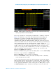
You should now see three digital waveforms captured by the scope’s digital
channels of acquisition similar to Figure 79. These I
2
S training signals are
being generated by the scope’s built-in pattern generator and routed
directly to the scope’s digital acquisition system; bypassing the logic probe.
Note that in a real measurement application such as this, you would use
the scope’s analog inputs and/or logic probe to capture these signals from
your system.
D9 is the audio serially encoded data signal (SDATA), D8 is the serial
clock signal (SCLK), and D7 is the Word Select signal (WS). Let’s now set
up the scope to decode these I
2
S signals.
12 Press the [Serial] front panel key.
13 Press the Mode I
2
C softkey; then select I
2
S using the Entry knob.
14 Press the Signals softkey.
15 Press the SCLK softkey; then select D8 as the clock source using the
Entry knob.
16 Press the WS softkey; then select D7 using the Entry knob.
17 Press the SDATA softkey; then select D9 using the Entry knob.
18 Press the (Back) front panel button to return to the previous menu.
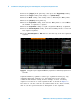
19 Press the Bus Config softkey; then verify that Word Size is set to “8”,
Receiver is set to “8”, Alignment is set to “Standard I
2
S”, WS Low is set to
“Left channel”, SCLK Slope is set “rising edge”.
Figure 79 Capturing I
2
S signals using the scope’s digital channels of acquisition (MSO).
Back