
Service manual


28 Agilent 382A Operating and Service Manual
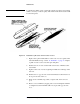
Replacement Parts List
14A End Section (without Resistive
Card)
P
X
K
4
R
4
3
3
3
3
00382-6000
7
00382-6000
9
00382-2000
7
00382-2001
4
2
2
2
2
0
0
0
0
14B End Section (with Resistive Card) P
X
K
4
R
4
3
3
3
3
00382-6000
8
00382-6001
0
00382-2001
2
00382-2001
1
2
2
2
2
1
1
1
1
15 Dial Knob
2
P, X 3 0370-0038 1 0
16 Worm Gear Shaft P, X 3 X382A-8 1 0
17 Dial Collar P, X 3 X382A-18 1 0
18 Dial P, X 3 J382A-23 1 1
19 Worm Gear Tension Adjustment
Spring
P, X 3 X382A-10 1 0
20 Worm Gear Thrust Adjustment
Spring
P, X 3 X382A-10 1 0
21 Offset Gear P, X 3 5020-0248 1 0
22 Stop Gear P, X 3 X382A-36 1 0
23 Ball Bearing, Rear Worm Gear
Shaft
P, X 2 1410-0007 1 0
24 Rear Bearing Mount
3
P, X 3 X382A-9 1 0
25 Resistive Card, End Section
3
P
X
K
4
R
4
3
3
3
3
P382A-3
X382A-24
K382A-21
B
K382A-21
B
2
2
2
2
1
1
1
1
26 Resistive Card, Center Section
3
P
X
3
3
P382A-4
X382A-43
1
1
1
1
1. See introduction to this section and Code List of Manufacturers, below.
2. When replacing the end section having the choke as a part of the end section, both the end section and the choke flange
must be ordered.
3. Item not shown in Figures 5 and 7.
4. These instruments are of different design and these are the only parts recommended for field replacement.
Reference
Item
Description Frequency Bands Mfr.
1
Agilent
Part No.
TQ
1
RS
1