
Service manual


Agilent 382A Operating and Service Manual 25
Maintenance
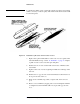
Figure 14 Application of Conductive Silver Paint o End Section
6. Install end card with emulsion (deposited) side up in recessed half of the
end section as shown in Figure 12.
7. Replace top half. Seat drive pins with pliers.
8. Install screws with heads up.
9. Check card for wrinkles. If necessary, remove wrinkles as described in
step 12 under “Center Section Resistive Card Replacement” on page20.
10. Install choke and/or bearing ring. Make sure parts are properly seated.
NOTE To replace only end-section card, complete steps 3 through 5, and 7.
Assembly 1. Turn dial fully clockwise.
2. Insert barrel so center card is rotated 1/32 inch beyond the horizontal as
noted in step 2 under “To Dismantle” on page17.
3. Replace end section drive pins from end section side.
4. Tighten end sections.
5. Do not adjust screws on the flat springs of rear bearing block.
6. Adjust ring nut (lock nut) on center barrel until snug. Then back off 1/8
turn.