
Service manual


Agilent 382A Operating and Service Manual 23
Maintenance
NOTE Do not remove pins; just loosen screws. Steps 5 through 12 must be
completed before silver paint dries (approximately 1/2 hour).
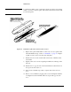
13. Refer to Figure 11. Apply conductive silver to seams of choke joint on
ends of center section.
Figure 11 Application of Silver Paint to Choke Joint of Center Section
NOTE Paint these ends well. Failure to do so will cause excessive insertion loss.
14. Replace "O" ring and ring nut. Small OD should be outboard on ring
nut.
NOTE To replace only end-section card, complete steps 1 through 10.
End Section Resistive
Card Replacement
1. Remove bearing ring and choke joint (light press fit).
NOTE Choke joint may be part of end section. In this case the choke joint cannot be
removed.