
Service manual


22 Agilent 382A Operating and Service Manual
Maintenance
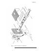
NOTE To identify the emulsion side, scratch the extreme edge (that portion which
will be covered by conductive paint). The emulsion side when scratched will
become transparent.
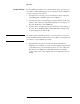
Figure 10 Installation of Resistive Card in Center Section
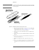
7. Replace drive pin in marked half of center section to act as guides. This
is the half marked in step 7 under “To Dismantle” on page17”. Replace
top half of center section. Seat drive pins with pliers.
8. Install screws in one side of barrel with screw heads on marked center
section half.
9. Tighten center section screws beginning in middle and working toward
each end.
10. Install screws on opposite side of barrel with heads in same direction as
in step 8. Leave this side loose.
11. Check card for wrinkles. If possible, compare with one known to be
good.
12. Remove excess wrinkles by tapping center section with plastic hammer
on untightened seam. If wrinkles still exist, repeat with opposite side
loose.