
Service manual


18 Agilent 382A Operating and Service Manual
Maintenance
NOTE Center card passes thru the horizontal and meets a stop approximately 1/32
of an inch beyond this point (as measured at edge of card).
3. Note position of flag with respect to dial. The flag should be at the
bottom of travel and the dial "0" (zero) should be to right of the center
line.
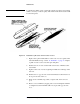
4. Loosen clamping screws on flag drive cable. Free flag.
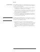
5. Drive locator pins to center of unit with punch. See Figure 7. Note: In
some models the drive pin is an integral part of the casting. If pins are
not visible from the outside, disregard step 5.
6. Remove the 8 screws holding the end section in place. Remove end
section.
7. With dial set to "0" (zero) mark top of center section as shown in Figure
7. Remove center section through end section opening.