Agilent Technologies 87050A Option K24 Multiport Test Set User’s and Service Guide Use this manual with these documents: 8719D/20D/22D Network Analyzer User’s Guide, Part Number 08720-90288 8753D Network Analyzer User’s Guide, Part Number 08753-90257 8753E Network Analyzer User’s Guide, Part Number 08753-90367 8719D/20D/22D Network Analyzer Service Guide, Part Number 08720-90292 8753D Network Analyzer Service Guide, Part Number 08753-90261 8753E Network Analyzer Service Guide, Part Number 08753-90374 Agi
Notices No part of this manual may be reproduced in any form or by any means (including electronic storage and retrieval or translation into a foreign language) without prior agreement and written consent from Agilent Technologies, Inc. as governed by United States and international copyright laws. Restricted Rights Legend Use, duplication, or disclosure by the U.S.
Contents 1. Agilent Technologies 87050A Option K24 Installing the Test Set . . . . . . . . . . . . . . . . . . . . . . . . . . . . . . . . . . . . . 1-2 Checking the Shipment . . . . . . . . . . . . . . . . . . . . . . . . . . . . . . . . . . 1-3 Meeting Electrical and Environmental Requirements. . . . . . . . . . 1-4 2. Getting Started Connecting and Turning on the Test Set . . . . . . . . . . . . . . . . . . . . . . Setting the Test Set Address Switch . . . . . . . . . . . . . . . . . . . . . . . . .
6. Service Performance Tests . . . . . . . . . . . . . . . . . . . . . . . . . . . . . . . . . . . . . . . . 6-2 Insertion Loss . . . . . . . . . . . . . . . . . . . . . . . . . . . . . . . . . . . . . . . . . . 6-3 Return Loss . . . . . . . . . . . . . . . . . . . . . . . . . . . . . . . . . . . . . . . . . . . . 6-3 Isolation. . . . . . . . . . . . . . . . . . . . . . . . . . . . . . . . . . . . . . . . . . . . . . . 6-4 Performance Test Record . . . . . . . . . . . . . . . . . . . . . . . . . . . . . . .
1 Agilent Technologies 87050A Option K24 The Agilent 87050A Option K24 multiport test set is designed for use with 50 Ω network analyzers such as the Agilent 8719, 8720, 8722, and 8753D/E. The test set provides the ability to make single connection, multiple measurements of multiport devices with up to 24 ports, such as distribution amplifiers, taps, switches and couplers. Throughput is increased by reducing the number of device reconnects the operator must perform.
Agilent Technologies 87050A Option K24 Installing the Test Set Installing the Test Set This chapter will guide you through the steps necessary to correctly and safely install your multiport test set. The steps are: 1. Check the Shipment 2.
Agilent Technologies 87050A Option K24 Installing the Test Set Checking the Shipment After the test set has been unpacked, you should keep the original packaging materials so they can be used if you need to transport the instrument. Check the items received against Table 1-1 to make sure that you have received everything. Inspect the test set and all accessories for any signs of damage that may have occurred during shipment.
Agilent Technologies 87050A Option K24 Installing the Test Set Meeting Electrical and Environmental Requirements 1. The line power module on your test set is an autoranging input. It is designed to be used with an ac power source with a nominal voltage of either 115 V or 230 V. 2. Ensure that the available ac power source meets the following requirements: • 90 to 250 Vac • 48 to 66 Hz • 40 watts CAUTION This product has an autoranging line voltage input.
Agilent Technologies 87050A Option K24 Installing the Test Set 4. Verify that the power cable is not damaged, and that the power source outlet provides a protective earth ground contact. Note that the Figure 1-1 depicts only one type of power source outlet. Refer to Figure 4-5 on page 4-7 to see the different types of power cord plugs that can be used with your test set.
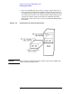
Agilent Technologies 87050A Option K24 Installing the Test Set 5. If you are installing the test set into a cabinet, ensure there are at least two inches of clearance around the sides and back of the test set and the system cabinet. See Figure 1-2. The convection into and out of the test set must not be restricted. The ambient temperature (outside the cabinet) must be less than the maximum operating temperature of the test set by 4 °C for every 100 watts dissipated in the cabinet.
Agilent Technologies 87050A Option K24 Installing the Test Set 6. Set up a static safe workstation. Electrostatic discharge (ESD) can damage or destroy components (refer to Figure 1-3).
Agilent Technologies 87050A Option K24 Installing the Test Set 1-8 User’s and Service Guide
2 Getting Started User’s and Service Guide 2-1
Getting Started Connecting and Turning on the Test Set Connecting and Turning on the Test Set The test set is designed to be placed underneath the network analyzer in a rack system and connected to it as shown in Figure 2-1. Use the two SMA 50 Ω jumper cables, part number 08720-20245, that were shipped with the test set. See Table 1-1 on page 1-3.
Getting Started Setting the Test Set Address Switch Setting the Test Set Address Switch The test set is shipped with the GPIB (HP-IB) address set to 12, which sets the parallel address to 0 as in Figure 2-2. Refer to Chapter 3 "Controlling the Test Set and Making Measurements" for the definition of the parallel address. To set the GPIB address, set all five switches so that the sum of the switches in the on or “1” position equal the desired address.
Getting Started Performing the Operator's Check Performing the Operator's Check For information on how to control the test set, refer to Chapter 3. Description The following operator's check is designed to provide you with a high degree of confidence that your test set is working properly. It is not designed to verify specifications. To verify specifications, refer to Chapter 6.
3 Controlling the Test Set and Making Measurements The Agilent 87050A Option K24 is a “slave” instrument: a controller must be used to control the test set.
Controlling the Test Set and Making Measurements Commands Commands As mentioned earlier, the test set can be controlled in three ways. The first two involve the use of a separate computer. The third way uses the network analyzer manually. These methods of control are detailed below and on the following page. Computer Control The first way to control the test set is to write GPIB commands to the network analyzer which then writes to the test set by way of the parallel port.
Controlling the Test Set and Making Measurements Commands Figure 3-1 Controlling the Test Set Over GPIB (HP-IB) NOTE Connection to the network analyzer is not required when controlling the test set over GPIB. Network Analyzer Control The third method of sending commands uses the network analyzer to control the test set directly. This method is performed with the standard setup of the network analyzer working with the test set.
Controlling the Test Set and Making Measurements Commands Table 3-1 Test Port Addresses Connection Path GPIB Command Decimal [D] Binary Equivalent Transmission to Port 1 tran_01 0 00000000 Transmission to Port 2 tran_02 1 00000001 Transmission to Port 3 tran_03 2 00000010 Transmission to Port 4 tran_04 3 00000011 Transmission to Port 5 tran_05 4 00000100 Transmission to Port 6 tran_06 5 00000101 Transmission to Port 7 tran_07 6 00000110 Transmission to Port 8 tran_08 7 0
Controlling the Test Set and Making Measurements Commands Table 3-1 Test Port Addresses Connection Path GPIB Command Decimal [D] Binary Equivalent Reflection to Port 5 refl_05 29 00011101 Reflection to Port 6 refl_06 30 00011110 Reflection to Port 7 refl_07 31 00011111 Reflection to Port 8 refl_08 32 00100000 Reflection to Port 9 refl_09 33 00100001 Reflection to Port 10 refl_10 34 00100010 Reflection to Port 11 refl_11 35 00100011 Reflection to Port 12 refl_12 36 001001
Controlling the Test Set and Making Measurements Commands To connect all ports to their internal 50 Ω loads, send the following two commands: OUTPUT 716;"PARAOUT24;" OUTPUT 716;"PARAOUT49;" or OUTPUT 712;"*t_term" OUTPUT 712;"*r_term" NOTE When a test set port is not in use, it is terminated in 50 Ω.
Controlling the Test Set and Making Measurements Commands Switch Count Commands To read the individual switch count, send the following two commands: OUTPUT 712;"SW10?" OUTPUT 712;J10$ The above example shows the J10 command only. To enter additional commands use Table 3-2.
Controlling the Test Set and Making Measurements Commands Table 3-2 Switch Count Commands J62 SW62? J63 SW63? J64 SW64? J65 SW65? J66 SW66? J67 SW67? J68 SW68? J69 SW69? J70 SW70? J71 SW71? J72 SW72? J73 SW73? 3-8 User’s and Service Guide
Controlling the Test Set and Making Measurements Calibrating the Test System Calibrating the Test System After the test set has warmed up for at least two hours, you should calibrate before making any measurements. Refer to your network analyzer user’s guide to determine the type of calibration appropriate for the measurements you will be making. You must calibrate each measurement path separately and store the calibration as an instrument state in the network analyzer.
Controlling the Test Set and Making Measurements Calibrating the Test System CAUTION When performing a full two-port calibration and making subsequent measurements, you must use the transfer switch internal to the 8720D to change the RF signal path direction. Do not use the test set to change the RF signal path direction when you are using a full two-port calibration. Doing so will render the calibration invalid.
Controlling the Test Set and Making Measurements Making Measurements Making Measurements The following examples assume that you are using a parallel port connection with an 8720D, with the test set's parallel address set to "0". See “Setting the Test Set Address Switch” on page 2-3 for information on setting the test set address. Measuring Transmission Refer to Figure 3-3 on page 3-12 for the following discussion.
Controlling the Test Set and Making Measurements Making Measurements Figure 3-3 Controlling the Test Set Measuring Reflection By leaving the DUT connected as in Figure 3-3 and setting the network analyzer to measure S11, you can measure reflection or return loss.
4 Front and Rear Panels This chapter contains information on the ports and switches found on the front and rear panels of the test set. This chapter is divided into two sections: front panel and rear panel.
Front and Rear Panels Front Panel Front Panel Figure 4-1 Front Panel Reflection 50 Ω Line Power Switch Port Connection Status LCD Transmission 50 Ω Test Ports 1–24 Ground Connector Line Power Switch The test set line power switch is located at the bottom left corner of the front panel. See Figure 4-1. The line power switch turns the power to the test set either on or off.
Front and Rear Panels Front Panel Figure 4-2 Physical Characteristics of 3.5 mm Connector The Transmission and Reflection Ports The Transmission and Reflection Ports are female 3.5 mm 50 Ω connectors. A 50 Ω cable connects directly to the Port 1/Port 2 or Reflection/Transmission port of the network analyzer using the cable, part number 08720-20245, that was shipped with your test set. CAUTION Check your analyzer documentation for damage limits to the RF OUT port.
Front and Rear Panels Rear Panel Rear Panel Figure 4-3 Rear Panel Parallel Port Input Printer/Test Set Switch Parallel Port Output Address Switch GPIB connector Line Module The Parallel Port Input Connector This input is connected to the network analyzer. The analyzer provides control signals that drive the switches inside the test set. In pass-through mode, it also accepts signals required to drive a printer.
Front and Rear Panels Rear Panel Address Switch The address switch sets the GPIB or parallel address of the test set. See “Setting the Test Set Address Switch” on page 2-3 for information. Line Module The line module contains the power cable receptacle and the line fuse. The line fuse and a spare reside within the line module. Figure 4-4 illustrates where the fuses are and how to access them.
Front and Rear Panels Power Cables Power Cables The line power cable is supplied in one of several configurations, depending on the destination of the original shipment. Each instrument is equipped with a three-wire power cable. When connected to an appropriate ac power receptacle, this cable grounds the instrument chassis. The type of power cable shipped with each instrument depends on the country of destination. See Figure 4-5 on page 4-7 for the part numbers of these power cables.
Front and Rear Panels Power Cables Figure 4-5 Power Cable and Line (Mains) Plug Part Numbers a Plug Type Cable Part Number 8120-8705 250V Plug b Length Description cm (in.
Front and Rear Panels Power Cables 4-8 User’s and Service Guide
5 Specifications Table 5-1 Agilent 87050A Option K24 Specifications Parameter Frequency Range Specification 50 MHz to 20 GHz Isolation 0.50 GHz to 1.3 GHz ≥85 dB 1.3 GHz to 3.0 GHz ≥100 dB 3.0 GHz to 6.0 GHz ≥95 dB Return Loss 0.50 GHz to 1.3 GHz ≥24 dB 1.3 GHz to 3.0 GHz ≥20 dB 3.0 GHz to 6.0 GHz ≥14 dB 6.0 GHz to 12.4 GHz ≥12 dB 12.4 GHz to 20 GHz ≥8 dB Insertion Loss 0.5 GHz to 6.0 GHz ≤2.5 dB 6.0 GHz to 12.4 GHz ≤3.5 dB 12.4 GHz to 20 GHz ≤4.
Specifications General Characteristics General Characteristics Environmental Characteristics General Conditions ESD (electrostatic discharge) must be eliminated by use of static-safe work procedures and an anti-static bench mat (such as part number 92175T).
Specifications General Characteristics Figure 5-1 Agilent 87050A Option K24 Physical Dimensions If you need technical assistance, contact Agilent Technologies. Refer to “Contacting Agilent Technologies” on page 7-6.
Specifications Agilent 87050A Option K24 Options Agilent 87050A Option K24 Options UK6 Option UK6 provides a commercial calibration certificate including actual test data. Data includes test results of 95 tests including reflection, transmission, and isolation from all test ports. Rack Ear Mounts Option 908, part number 5062-3974, provides rack mounts that make it quick and easy to install or remove the test set from a mainframe. For further information on these options please contact Agilent Technologies.
6 Service This chapter contains information on how to verify the performance of your test set, how to troubleshoot it if necessary, the theory of operation and a block diagram. Please read all applicable safety warnings and cautions in Chapter 7 before servicing the test set.
Service Performance Tests Performance Tests Performance testing consists of measuring insertion loss, return loss, and isolation between all ports. For the most accurate measurements, the use of an Agilent 8720D 50 Ω network analyzer is recommended and its use is assumed in these notes. Familiarity with RF/microwave measurements is also assumed. The use of adapters may be required and their effects should be accounted for.
Service Performance Tests Insertion Loss Step 1. Recall the full two-port calibration. Step 2. Connect the cable that is attached to Port 1 of the 8720D to the Transmission port of the 87050A Option K24. Step 3. Connect the cable from Port 2 of the analyzer to Port 1 of the 87050A Option K24. Select Transmission Port 1 using the 8720D. Record the results in the Performance Test Record, Table 6-1 beginning on page 6-6. Step 4. Repeat step 3 for each of the remaining test ports 2 through 24. Step 5.
Service Performance Tests Isolation Isolation needs to be measured only on adjacent ports. Two 50 Ω loads are required for this test. Step 1. Recall the full two-port calibration. Make sure the calibration is active and that averaging is “on” when making measurements. Step 2. Connect a 50 Ω load to both the Transmission and Reflection ports of the 87050A Option K24. Step 3. Connect the two cables that are attached to the network analyzer to Ports 1 and 2 of the 87050A Option K24.
Service Performance Tests Performance Test Record NOTE The following pages (Performance Test Record) are designed to be duplicated and used as a template for either of the Transmission or Reflection ports during each of the performance tests (Insertion Loss, Return Loss, and Isolation). At the top of each page, circle the appropriate input port (Transmission or Reflection), and write in the test date.
Service Performance Tests Transmission / Reflection Table 6-1 Date _______________ Agilent 87050A Option K24 Insertion Loss Test Record Test Description Port Minimum Specifications Measured Results Measured Uncertainty Port 1 ≤2.5 dB ___________ ±0.3 dB Port 2 ≤2.5 dB ___________ ±0.3 dB Port 3 ≤2.5 dB ___________ ±0.3 dB Port 4 ≤2.5 dB ___________ ±0.3 dB Port 5 ≤2.5 dB ___________ ±0.3 dB Port 6 ≤2.5 dB ___________ ±0.3 dB Port 7 ≤2.5 dB ___________ ±0.
Service Performance Tests Transmission / Reflection Table 6-1 Date _______________ Agilent 87050A Option K24 Insertion Loss Test Record Test Description Port Minimum Specifications Measured Results Measured Uncertainty Port 1 ≤3.5 dB ___________ ±0.3 dB Port 2 ≤3.5 dB ___________ ±0.3 dB Port 3 ≤3.5 dB ___________ ±0.3 dB Port 4 ≤3.5 dB ___________ ±0.3 dB Port 5 ≤3.5 dB ___________ ±0.3 dB Port 6 ≤3.5 dB ___________ ±0.3 dB Port 7 ≤3.5 dB ___________ ±0.
Service Performance Tests Transmission / Reflection Table 6-1 Date _______________ Agilent 87050A Option K24 Insertion Loss Record Test Description Port Minimum Specifications Measured Results Measured Uncertainty Port 1 ≤4.5 dB ___________ ±0.3 dB Port 2 ≤4.5 dB ___________ ±0.3 dB Port 3 ≤4.5 dB ___________ ±0.3 dB Port 4 ≤4.5 dB ___________ ±0.3 dB Port 5 ≤4.5 dB ___________ ±0.3 dB Port 6 ≤4.5 dB ___________ ±0.3 dB Port 7 ≤4.5 dB ___________ ±0.3 dB Port 8 ≤4.
Service Performance Tests Transmission / Reflection Table 6-2 Date _______________ Agilent 87050A Option K24 Return Loss Test Record Test Description Port Minimum Specifications Measured Results Measured Uncertainty Port 1 ≥24 dB ___________ ±1.5 dB Port 2 ≥24 dB ___________ ±1.5 dB Port 3 ≥24 dB ___________ ±1.5 dB Port 4 ≥24 dB ___________ ±1.5 dB Port 5 ≥24 dB ___________ ±1.5 dB Port 6 ≥24 dB ___________ ±1.5 dB Port 7 ≥24 dB ___________ ±1.
Service Performance Tests Transmission / Reflection Table 6-2 Date _______________ Agilent 87050A Option K24 Return Loss Test Record Test Description Port Minimum Specifications Measured Results Measured Uncertainty Port 1 ≥20 dB ___________ ±1.5 dB Port 2 ≥20 dB ___________ ±1.5 dB Port 3 ≥20 dB ___________ ±1.5 dB Port 4 ≥20 dB ___________ ±1.5 dB Port 5 ≥20 dB ___________ ±1.5 dB Port 6 ≥20 dB ___________ ±1.5 dB Port 7 ≥20 dB ___________ ±1.
Service Performance Tests Transmission / Reflection Table 6-2 Date _______________ Agilent 87050A Option K24 Return Loss Test Record Test Description Port Minimum Specifications Measured Results Measured Uncertainty Port 1 ≥14 dB ___________ ±0.6 dB Port 2 ≥14 dB ___________ ±0.6 dB Port 3 ≥14 dB ___________ ±0.6 dB Port 4 ≥14 dB ___________ ±0.6 dB Port 5 ≥14 dB ___________ ±0.6 dB Port 6 ≥14 dB ___________ ±0.6 dB Port 7 ≥14 dB ___________ ±0.
Service Performance Tests Transmission / Reflection Table 6-2 Date _______________ Agilent 87050A Option K24 Return Loss Test Record Test Description Port Minimum Specifications Measured Results Measured Uncertainty Port 1 ≥12 dB ___________ ±0.5 dB Port 2 ≥12 dB ___________ ±0.5 dB Port 3 ≥12 dB ___________ ±0.5 dB Port 4 ≥12 dB ___________ ±0.5 dB Port 5 ≥12 dB ___________ ±0.5 dB Port 6 ≥12 dB ___________ ±0.5 dB Port 7 ≥12 dB ___________ ±0.
Service Performance Tests Transmission / Reflection Table 6-2 Date _______________ Agilent 87050A Option K24 Return Loss Record Test Description Port Minimum Specifications Measured Results Measured Uncertainty Port 1 ≥8 dB ___________ ±0.5 dB Port 2 ≥8 dB ___________ ±0.5 dB Port 3 ≥8 dB ___________ ±0.5 dB Port 4 ≥8 dB ___________ ±0.5 dB Port 5 ≥8 dB ___________ ±0.5 dB Port 6 ≥8 dB ___________ ±0.5 dB Port 7 ≥8 dB ___________ ±0.5 dB Port 8 ≥8 dB ___________ ±0.
Service Performance Tests Transmission / Reflection Table 6-3 Date _______________ Agilent 87050A Option K24 Isolation Test Record Test Description Port Minimum Specifications Measured Results Measured Uncertainty Port 1 ≥85 dB ___________ ±5 dB Port 2 ≥85 dB ___________ ±5 dB Port 3 ≥85 dB ___________ ±5 dB Port 4 ≥85 dB ___________ ±5 dB Port 5 ≥85 dB ___________ ±5 dB Port 6 ≥85 dB ___________ ±5 dB Port 7 ≥85 dB ___________ ±5 dB Port 8 ≥85 dB ___________ ±5 dB
Service Performance Tests Transmission / Reflection Table 6-3 Date _______________ Agilent 87050A Option K24 Isolation Test Record Test Description Port Minimum Specifications Measured Results Measured Uncertainty Port 1 ≥100 dB ___________ ±5 dB Port 2 ≥100 dB ___________ ±5 dB Port 3 ≥100 dB ___________ ±5 dB Port 4 ≥100 dB ___________ ±5 dB Port 5 ≥100 dB ___________ ±5 dB Port 6 ≥100 dB ___________ ±5 dB Port 7 ≥100 dB ___________ ±5 dB Port 8 ≥100 dB ___________
Service Performance Tests Transmission / Reflection Table 6-3 Date _______________ Agilent 87050A Option K24 Isolation Test Record Test Description Port Minimum Specifications Measured Results Measured Uncertainty Port 1 ≥95 dB ___________ ±5 dB Port 2 ≥95 dB ___________ ±5 dB Port 3 ≥95 dB ___________ ±5 dB Port 4 ≥95 dB ___________ ±5 dB Port 5 ≥95 dB ___________ ±5 dB Port 6 ≥95 dB ___________ ±5 dB Port 7 ≥95 dB ___________ ±5 dB Port 8 ≥95 dB ___________ ±5 dB
Service Performance Tests Transmission / Reflection Table 6-3 Date _______________ Agilent 87050A Option K24 Isolation Test Record Test Description Port Minimum Specifications Measured Results Measured Uncertainty Port 1 ≥90 dB ___________ ±7 dB Port 2 ≥90 dB ___________ ±7 dB Port 3 ≥90 dB ___________ ±7 dB Port 4 ≥90 dB ___________ ±7 dB Port 5 ≥90 dB ___________ ±7 dB Port 6 ≥90 dB ___________ ±7 dB Port 7 ≥90 dB ___________ ±7 dB Port 8 ≥90 dB ___________ ±7 dB
Service Assembly Replacement and Post-Repair Procedures Assembly Replacement and Post-Repair Procedures The following table contains the list of replaceable parts for the Agilent 87050A Option K24 test set. If any of these parts or assemblies is replaced, you must run all performance tests to verify conformance to specifications.
Service Assembly Replacement and Post-Repair Procedures Table 6-4 NOTE Agilent 87050A Option K24 Replaceable Parts Replacement Part Part Number Quantity RF Cable- Sw A1-2 87050-20088 1 RF Cable- Sw A2-2 87050-20089 1 RF Cable- Sw A3-2 87050-20090 1 RF Cable- Sw A7-2 87050-20091 1 RF Cable- Sw A8-2 87050-20092 1 RF Cable- Sw A9-2 87050-20093 1 RF Cable- Sw A13-2 87050-20094 1 RF Cable- Sw A14-2 87050-20095 1 RF Cable- Sw A15-2 87050-20096 1 RF Cable- Sw A19-2 87050-20097 1
Service Assembly Replacement and Post-Repair Procedures NOTE Special options are built to order, therefore long lead times may be encountered when ordering replacement parts. WARNING Some parts in the instrument have sharp edges. Work carefully to avoid injury. CAUTION Before replacing an assembly or board, inspect for obvious, easily repaired defects such as bent pins on ICs or cold solder joints. Connector Replacement The 50 Ω 3.5 mm connectors are available separately as part number 5062-6618.
Service Troubleshooting and Block Diagram Troubleshooting and Block Diagram This section contains information on troubleshooting the test set to the assembly level only. By following these procedures you should be able to determine whether the power supply, front panel, or main switch board needs replacing. A block diagram is included at the end of this section as an aid in troubleshooting. Theory of operation information can be found in the next section of this manual.
Service Troubleshooting and Block Diagram Troubleshooting the Front Panel Board Turn the instrument power on and check the following: Step 1. Check the condition of each of the switching paths by issuing commands to switch each of the paths to either the transmission or reflection path. Ensure that the LCD indicates the appropriate path. Step 2. If the LCD indicates a wrong path, the problem can lie either with the front panel board or with the main switch board.
Service Troubleshooting and Block Diagram Figure 6-1 Agilent 87050A Option K24 Block Diagram User’s and Service Guide 6-23
Service Theory of Operation Theory of Operation The theory of operation begins with a general description of the 87050A Option K24 multiport test set. This is followed by more detailed operating theory. The operation of each group is described briefly, to the assembly level only. Detailed component level circuit theory is not provided. System Theory The test set consists of three main components: a power supply, a front panel display, and a controller interface mother board.
Service Theory of Operation A3 Controller Board (Mother Board) and Switch Driver Board (Daughter Board) Theory Refer to Figure 6-1 on page 6-23 for the following discussion. The mother and daughter board provide the bias to switch the paths of the various ports to the Transmission and Reflection ports. The front panel display contains an LCD that indicates the switched ports. A particular test port (1 through 24) can be in one of three states.
Service Theory of Operation 6-26 User’s and Service Guide
7 Safety and Regulatory Information User’s and Service Guide 7-1
Safety and Regulatory Information Safety and Regulatory Information Safety and Regulatory Information Introduction Review this product and related documentation to familiarize yourself with safety markings and instructions before you operate the instrument. This product has been designed and tested in accordance with international standards. Cleaning Instructions Clean the instrument cabinet using a damp cloth only.
Safety and Regulatory Information Safety and Regulatory Information Safety Information Warnings WARNING The WARNING notice denotes a hazard. It calls attention to a procedure, practice, or the like, which if not correctly performed or adhered to, could result in personal injury. Do not proceed beyond a WARNING notice until the indicated conditions are fully understood and met. Warnings applicable to this instrument are: WARNING No operator serviceable parts inside.
Safety and Regulatory Information Safety and Regulatory Information Cautions CAUTION The CAUTION notice denotes a hazard. It calls attention to an operating procedure, practice, or the like, which if not correctly performed or adhered to, could result in damage to the product or loss of important data. Do not proceed beyond a CAUTION notice until the indicated conditions are fully understood and met.
Safety and Regulatory Information Safety and Regulatory Information Instrument Markings ! When you see this symbol on your instrument, you should refer to the instrument’s instruction manual for important information. This symbol indicates hazardous voltages. The laser radiation symbol is marked on products that have a laser output. This symbol indicates that the instrument requires alternating current (ac) input. The CE mark is a registered trademark of the European Community.
Safety and Regulatory Information Contacting Agilent Technologies Contacting Agilent Technologies A current list of Agilent Technologies Sales and Service Offices can be accessed on the internet at http://www.agilent.com/find/assist. If you do not have access to the internet, refer to the information below to contact your nearest Agilent Technologies representative. Online assistance: www.agilent.