
User`s guide


User’s and Service Guide 11
87050A Option K24 Front and Rear Panel Features
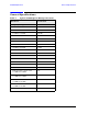
Figure 5 Rear Panel
Parallel Port Input Connector
This input is connected to the network analyzer. The analyzer provides control signals that
drive the switches inside the test set. In pass-through mode, it also accepts signals
required to drive a printer.
Parallel Port Output Connector
The output from this connector is used either to control another test set, or to control a
printer, depending upon how the Printer/Test Set switch is set.
Printer/Test Set Switch
This switch determines the function of the Parallel Port Output connector. When switched
to Printer, the Parallel Port Output will pass through printer driver signals. When
switched to Test Set, an additional test set can be controlled from the Parallel Port Output
connector.
GPIB Connector
This connector allows the test set to be connected directly to a controller, as shown in
Figure 5.
Parallel Port Input
Parallel Port Output
Printer/Test Set
Switch
GPIB connector
Address Switch
Line Module