
Technical data


340 Agilent InfiniiVision 2000 X-Series Oscilloscopes Programmer's Guide
20 :MEASure Commands
Introduction to
:MEASure
Commands
The commands in the MEASure subsystem are used to make parametric
measurements on displayed waveforms.
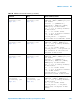
Measurement Setup
To make a measurement, the portion of the waveform required for that
measurement must be displayed on the oscilloscope screen.
Measurement Error
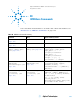
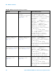
n/a :MEASure:VTIMe?
<vtime>[,<source>]
(see page 374)
<vtime> ::= displayed time from
trigger in seconds in NR3 format
<source> ::= {CHANnel<n> |
FUNCtion | MATH | WMEMory<r>} for
DSO models
<source> ::= {CHANnel<n> |
DIGital<d> | FUNCtion | MATH |
WMEMory<r>} for MSO models
<n> ::= 1 to (# analog channels)
in NR1 format
<r> ::= 1-2 in NR1 format
<d> ::= 0 to (# digital channels
- 1) in NR1 format
<return_value> ::= voltage at the
specified time in NR3 format
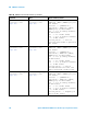
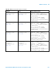
:MEASure:VTOP
[<source>] (see
page 375)
:MEASure:VTOP?
[<source>] (see
page 375)
<source> ::= {CHANnel<n> |
FUNCtion | MATH | WMEMory<r>}
<n> ::= 1 to (# analog channels)
in NR1 format
<r> ::= 1-2 in NR1 format
<return_value> ::= voltage at the
top of the waveform in NR3 format
:MEASure:WINDow
<type> (see page 376)
:MEASure:WINDow? (see
page 376)
<type> ::= {MAIN | ZOOM | AUTO}
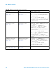
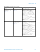
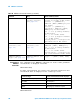
Table 70 :MEASure Commands Summary (continued)
Command Query Options and Query Returns
Measurement Type Portion of waveform that must be displayed
period, duty cycle, or frequency at least one complete cycle
pulse width the entire pulse
rise time rising edge, top and bottom of pulse
fall time falling edge, top and bottom of pulse