
Technical data


6Repair Guide
86 N1911A/1912A P-Series Power Meters Service Guide
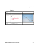
• Remove the PSU (Figure 6-5): Use the T10
Torx screwdriver bit to remove the 6 screws
attaching the PSU to the top clamshell. Lift
and remove the PSU.
Figure 6-5
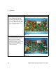
• Key to Figure 6-6 and Figure 6-7:
1 Front panel assembly
2 Calibrator assembly
3 Sensor RF connections
4 Sensor flex connection(s)
5 Calibrator cable connection
6 Cable clamp
7 Rear panel assembly
8 Line module
9 Fan assembly
10 Analog recorder output connection(s)
11 Service connector cable
12 Ribbon cable
13 PPMC assembly
14 DAP assembly (Channel A)
15 DAP assembly (Channel B)
Figure 6-6
Instructions Visual
12
9
8
10
7
13
14
15
6
5
4
3
1
2
11