
System information


8
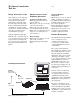
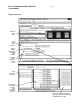
Theory of Operation
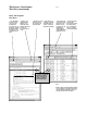
The logic analyzer probes the par-
allel data buses in the system, such
as the UTOPIA shown above. The
logic analyzer needs access to data
signals, qualifying signals, start of
cell or packet bit, and the synchro-
nous clock for the bus.
With access to the "Start of Cell"
or "Start of Packet" bit on the data
bus, the logic analyzer starts look-
ing at the beginning of a cell or
packet. With the protocol defini-
tion set up by the user, the logic
analyzer can sequence down into
the cell or packet to find the de-
sired protocol fields to trigger on.
Qualifiers such as "Data Valid"
allow the logic analyzer to sample
only on events of interest instead
of all cycles. The synchronous bus
clock samples the data into the
logic analyzer.
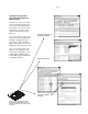
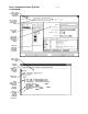
Protocol Support
The B4640B includes both ATM
and Ethernet standard protocol
setup files. These files can be
edited to support custom fields or
"wrapper" layers in a protocol.
Custom additions or changes can
be easily entered through the logic
analyzer user interface or a text
file, as shown on page 9. These
custom protocol definitions are
used in both the trigger definition
and packet display.
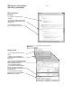
Figure 3: Typical ATM Switch Design.
Data Communications Tool Set
(continued)
Switch
Fabric
CPU
ATM
Layer
ATM
Layer
ATM
Layer
ATM
Layer
PHY
PHY
PHY
PHY
PHY
PHY
PHY
UTOPIA Level 2
Custom / UTOPIA
UTOPIA
Level 1