
Specifications

83
Chapter 1: Agilent Technologies 16700A/B-Series Logic Analysis System
Using a Timing Analyzer and an Oscilloscope
Using a Timing Analyzer and an Oscilloscope
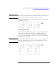
In the following example we use an oscilloscope to trigger on a glitch
and a timing analyzer to capture bus data after the glitch. Both the
timing waveforms and the glitch are time-correlated and displayed in
the same display.
NOTE: Before you begin configuring the measurement, connect the appropriate
probing (see page 177) for your measurement.
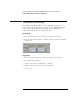
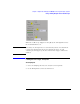
1. From the System window, select the oscilloscope icon, then select
Display....
2. From the oscilloscope window that appears, configure the oscilloscope
(see page 84) to trigger on a glitch.
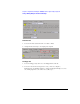
3. From the System window, select the logic analyzer icon, then select
Setup....
4. From the analyzer window, configure the analyzer (see page 85) to trigger
on the first occurrence of data.
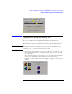
5. From the Icon Bar in the System window, select the Intermodule icon.
6. From the Intermodule window, configure the Group Run Arming Tree (see
page 87) so the Group Run field arms the oscilloscope and the
oscilloscope arms the logic analyzer.
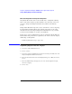
7. From the Intermodule window, select the Navigate icon, then Analyzer N
(N=the slot analyzer is in), then Waveform....
8. From the Waveform display that appears, select the Mixed Signal tab.
9. From the Mixed Signal tab, import the oscilloscope signal (see page 88)
into the Waveform display.
10. From the menu bar in the Waveform display, select Options..., then select
Reference trigger..., then select the oscilloscope as the trigger reference.
11. Select the Run Single icon to run the measurement.