Help Volume © 1992-2002 Agilent Technologies. All rights reserved.
Agilent Technologies 16700A/B-Series Logic Analysis System • Making Measurements (see page 12) - Setting up a measurement, loading a config file, etc. • Measurement Examples (see the Measurement Examples help volume) Setting up common measurements. • Using Measurement Tools (see page 18) - Instrument, Analysis, Display, Emulation and Utility tools. • System Overview (see page 28) - Getting to know your logic analysis system.
Agilent Technologies 16700A/B-Series Logic Analysis System The Intermodule Window (see page 65) The Intermodule window graphically depicts the internal arming sequence between measurement modules and any external trigger connections to a target system. With multiple instrument measurements, use the Intermodule window to adjust the order of trigger arming, and to compensate for timing skew between the modules.
Agilent Technologies 16700A/B-Series Logic Analysis System The System Administration Tools (see page 117) Use the System Administration tools to set up system defaults, configure network connections, and perform maintenance on the operating system file set.
Contents Agilent Technologies 16700A/B-Series Logic Analysis System 1 Agilent Technologies 16700A/B-Series Logic Analysis System Making Measurements 12 Overview - Starting a New Measurement Automatic Measurement Configuration 13 14 Using the Target Control Port 15 Using the Agilent 16701A/B Expansion Frame Master List of All Tool Help Volumes Japanese Help Volumes System Overview 17 18 23 28 Frame Specifications and Characteristics What is a Specification 29 What is a Characteristic 29 What is a C
Contents Available Help Resources Information on the Web System Terminology 42 42 43 File Management Tools 44 To load configuration files 45 To save configuration files 47 To automatically load a file at startup 49 To copy files 49 To delete files 49 To move files 50 To rename files 50 To compress/uncompress files - PKZIP/PKUNZIP To create directories 52 To delete directories 53 To rename directories 53 To format floppy disks 53 To refresh the File Manager 54 To mount an external hard drive 54 File
Contents The Intermodule Window 65 Overview - Multiple Instrument Configuration Overview - Multiple Analyzer Configuration Overview - Multiple Frames Configuration 67 69 71 One frame; Two analyzers; Group Run OR Trigger 76 One frame; Three analyzers; Group Run OR Trigger 76 Two frames; Two analyzers; Group Run OR Trigger 76 Two frames; Three analyzers; Group Run OR Trigger 77 Three frames; Three analyzers; Group Run and Group Run OR Trigger Three frames; Three analyzers; Group Run OR Trigger 78 Two fr
Contents Adjusting Intermodule Skew 101 Configure the Timing Analyzer 102 Configure the Oscilloscope 103 Configure the Group Run Arming Tree 104 Configure the Waveform Display 105 Placing Markers for an Interval Reading.
Contents The System Administration Tools 117 Setting Up on a Network 118 Setting Up Emulation Probes/Modules on a Network 125 Mapping Windows Network Drives 126 Sharing Logic Analysis System Directories 131 Mounting an NFS File System 135 Mounting a ClearCase View 138 Using FTP (File Transfer Protocol) 140 Using Ping 142 Using Telnet 142 Troubleshooting the 100BaseT Lan Connection 143 Licensing Policy for the Logic Analysis System 144 Printing Windows - Configurations 145 Printer Setup 146 Print Options
Contents Accessing Display Tools Editing Colors 182 Using Symbols 183 181 To load object file symbols 184 To adjust symbol values for relocated code To create user-defined symbols 186 To enter symbolic label values 187 To create an ASCII symbol file 188 To create a readers.
1 Agilent Technologies 16700A/B-Series Logic Analysis System 11
Chapter 1: Agilent Technologies 16700A/B-Series Logic Analysis System Making Measurements Making Measurements • Overview - Starting a New Measurement (see page 13) • Loading Configuration Files (see page 45) • Changing a Configuration (see page 59) • Saving Configuration Files (see page 47) • Multiple Instrument Measurements (see page 65) • The Setup Assistant (see the Setup Assistant help volume) • Using Markers in the Display Tools (see the Markers help volume) • “Using the Target Control
Chapter 1: Agilent Technologies 16700A/B-Series Logic Analysis System Overview - Starting a New Measurement Overview - Starting a New Measurement This overview shows how the graphical interface is used to configure the logic analysis system for simple measurements. 1. Connect the appropriate probing (see page 177) to your target system. 2. From the System window, (see page 14) select the desired Instrument tool icon, then select Setup. When you select a tool icon and select Setup, two things occur.
Chapter 1: Agilent Technologies 16700A/B-Series Logic Analysis System Automatic Measurement Configuration Automatic Measurement Configuration 14
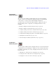
Chapter 1: Agilent Technologies 16700A/B-Series Logic Analysis System Using the Target Control Port Using the Target Control Port The Target Control Port is an 8-bit, TTL port that you can use to send signals to your target system. It does not function like a pattern generator, but more like a remote control for the target's switches. Connecting the Target Control The target control cable is keyed, so it can be inserted only one way.
Chapter 1: Agilent Technologies 16700A/B-Series Logic Analysis System Using the Target Control Port 4. Set Output Drive to Open Collector. 5. When the target needs to be reset manually, select Pulse. About Open Collector and Active Drive Open Collector functions as a tri-state, with a logic "1" being highimpedance, and a logic "0" sinking a current of up to 12 milliamps. Active Drive puts out a standard TTL signal with 1 high and 0 low.
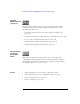
Chapter 1: Agilent Technologies 16700A/B-Series Logic Analysis System Using the Agilent 16701A/B Expansion Frame Using the Agilent 16701A/B Expansion Frame The Agilent Technologies 16700A/B-series logic analysis systems can be expanded to a total of ten slots by connecting an 16701A/B expander frame. When connected, the two frames create a tightly coupled system fully controlled by the 16700A/B. Expanded System Features • Combined total of ten module slots.
Chapter 1: Agilent Technologies 16700A/B-Series Logic Analysis System Master List of All Tool Help Volumes Master List of All Tool Help Volumes All Instrument, Display, Utility, and Analysis tools, have their own specific help volume. The Help menu within each tool window accesses its own help volume. You can access specific Tool Help Volumes below, or, you can return to the Main Help Volume.
Chapter 1: Agilent Technologies 16700A/B-Series Logic Analysis System Master List of All Tool Help Volumes • 16712A Logic Analyzer (see the Agilent Technologies 16712 128K sample Logic Analyzer help volume) • 16715A Logic Analyzer (see the Agilent Technologies 16715A 167 MHz State/667 MHz Timing Logic Analyzer help volume) • 16716A Logic Analyzer (see the Agilent Technologies 16716A 167 MHz State/2 GHz Timing Zoom Logic Analyzer help volume) • 16717A Logic Analyzer (see the Agilent Technologies 1671
Chapter 1: Agilent Technologies 16700A/B-Series Logic Analysis System Master List of All Tool Help Volumes • 16760A Logic Analyzer (see the Agilent Technologies 16760A 1500 Mb/s State/800 MHz Timing Logic Analyzer help volume) The Display Tools • Listing Display (see the Listing Display Tool help volume) • Waveform Display (see the Waveform Display Tool help volume) • Chart Display (see the Chart Display Tool help volume) • Distribution Display (see the Distribution Display Tool help volume) See
Chapter 1: Agilent Technologies 16700A/B-Series Logic Analysis System Master List of All Tool Help Volumes • NOTE: System Performance Analysis - SPA (see the System Performance Analyzer help volume) If an add-on tool is not installed, you will see a message stating that the help volume could not be found. If you wish to purchase any of these add-on toolsets, call your local Agilent Technologies sales representative.
Chapter 1: Agilent Technologies 16700A/B-Series Logic Analysis System Master List of All Tool Help Volumes • Emulation - Pentium® (see the Emulation: Pentium and Pentium w/ MMX Technology help volume) • Emulation - Pentium® Pro (see the Emulation: Pentium Pro and Pentium II Processor family help volume) • Emulation - PowerPC 4xx (see the Emulation: PowerPC 4xx help volume) • Emulation - PowerPC 500 (see the Emulation: PowerPC 5xx help volume) • Emulation - PowerPC 60x (see the Emulation: PowerPC 6
Chapter 1: Agilent Technologies 16700A/B-Series Logic Analysis System Japanese Help Volumes Japanese Help Volumes A portion of the online help system has been localized to Japanese. • To view available Japanese help from a product window "Help" button, select "Select Help Language -> Japanese" from the "Help" pulldown in the workspace window. (If Japanese help is not available, English help will be displayed.
Chapter 1: Agilent Technologies 16700A/B-Series Logic Analysis System Japanese Help Volumes help volume) • 24 Instruments: • 16517A/18A 4 GHz Timing/1 GHz State Logic Analyzer (Japanese) (see the Agilent Technologies 16517A 4GHz Timing/1GHz State Logic Analyzer (Japanese) help volume) • Using the 16522A Pattern Generator (Japanese) (see the Agilent Technologies 16522A 200 MHz Pattern Generator (Japanese) help volume) • 16533A/34A Digitizing Oscilloscope (Japanese) (see the Agilent Technologies 16533
Chapter 1: Agilent Technologies 16700A/B-Series Logic Analysis System Japanese Help Volumes volume) • 16712A 128K Sample Logic Analyzer (Japanese) (see the Agilent Technologies 16712 128K sample Logic Analyzer (Japanese) help volume) • 16715A 167 MHz State/667 MHz Timing Logic Analyzer (Japanese) (see the Agilent Technologies 16715A 167 MHz State/667 MHz Timing Logic Analyzer (Japanese) help volume) • 16716A 167 MHz State/2 GHz Timing Zoom Logic Analyzer (Japanese) (see the Agilent Technologies 16716A
Chapter 1: Agilent Technologies 16700A/B-Series Logic Analysis System Japanese Help Volumes • • • • 26 Display Tools: • Using the Listing Tool (Japanese) (see the Listing Display Tool (Japanese) help volume) • Using the Chart Tool (Japanese) (see the Chart Display Tool (Japanese) help volume) • Using the Distribution Tool (Japanese) (see the Distribution Display Tool (Japanese) help volume) • Using the Digital Waveform Tool (Japanese) (see the Waveform Display Tool (Japanese) help volume) • W
Chapter 1: Agilent Technologies 16700A/B-Series Logic Analysis System Japanese Help Volumes help volume) • Emulation: • Setting Up and Starting Emulation Control (Japanese) (see the Emulation: Setting Up (Japanese) help volume) • Using the SH7750 Emulation Control Interface (Japanese) (see the Emulation: Hitachi SH7750 (Japanese) help volume) • Using the TX19/39 Emulation Control Interface (Japanese) (see the Emulation: Toshiba TX19/39 (Japanese) help volume) To return to the main English help syste
Chapter 1: Agilent Technologies 16700A/B-Series Logic Analysis System System Overview System Overview • Product Description (see page 32) • The User Interface - Icons, Tabs, and Navigation (see page 34) • Session Control and the User Environment (see page 172) • “Frame Specifications and Characteristics” on page 28 • “How the Help System is Accessed” on page 30 See Also NOTE: List of Tool Help Volumes (see page 18) For information on product Warranty and Safety Considerations, refer to the hardc
Chapter 1: Agilent Technologies 16700A/B-Series Logic Analysis System System Overview 149 degrees F) - Humidity Instrument, probe lead sets, and cables: 8 to 80% relative humidity at 40 degrees C (+104 degrees F) - Altitude To 3000 m (10,000 ft) - Vibration Operating: Random vibration 5-500 Hz, 10 minutes per axis, approximately 0.2 g rms Nonoperating: Random vibration 5 to 500 Hz, 10 minutes per axis, approximately 2.41 g rms; and swept sine resonant search, 5 to 500 Hz, 0.
Chapter 1: Agilent Technologies 16700A/B-Series Logic Analysis System System Overview procedures are traceable and must specify adequate calibration standards. Calibration procedures verify products meet the specifications by comparing measured parameters against a pass-fail limit. The pass-fail limit is the specification less any required guardband.
Chapter 1: Agilent Technologies 16700A/B-Series Logic Analysis System System Overview On the Main System Open Second Help Window (English) Open Second Help Window (Japanese) Select Help Language Tool Windows From Help in the menu bar you have access to the following topics: On this Window On the Main System Configuration Dialogs Any Help field located at the bottom of a dialog, accesses help for that dialog only. Help on Help The Help field in any Help dialog, accesses help on using help.
Chapter 1: Agilent Technologies 16700A/B-Series Logic Analysis System Product Description Product Description The Agilent Technologies 16700A/B-Series logic analysis systems are a scalable family of frames that allow you to time-correlate measurements across domains from analog signals to source code. Included in the 16700A/B frames is an integrated Web server and Home Page.
Chapter 1: Agilent Technologies 16700A/B-Series Logic Analysis System Product Description buttons and knobs.
Chapter 1: Agilent Technologies 16700A/B-Series Logic Analysis System The User Interface - Icons, Tabs, and Navigation The User Interface - Icons, Tabs, and Navigation The user interface is designed to help you quickly configure measurements and navigate between windows. Depending on the model, your system will have either an integrated display (16702A & 16702B), or would require you to connect a remote display (16700A & 16700B). The user can interact with all systems with a mouse and keyboard.
Chapter 1: Agilent Technologies 16700A/B-Series Logic Analysis System The User Interface - Icons, Tabs, and Navigation The Window Menu Pick The Window pick appears in the menu bar at the top of all tool windows. Select Window, then select the desired category type. Your choices are System windows or measurement module windows. The System Icon Bar The System Icon Bar is located at the top of the main System window as well as all other tool windows.
Chapter 1: Agilent Technologies 16700A/B-Series Logic Analysis System The User Interface - Icons, Tabs, and Navigation Using the 16702B Knobs and Buttons The front panel knobs and buttons are used as quick shortcuts for the most commonly used interface operations. Run/Stop buttons The front panel Run/Stop buttons apply to the currently focused window. The currently focused window will always have the blue titlebar. The run mode is the same as what is designated by the run icons in the icon bar.
Chapter 1: Agilent Technologies 16700A/B-Series Logic Analysis System The User Interface - Icons, Tabs, and Navigation Global marker knobs Quickly change the position of the global G1 and G2 markers in the display tool windows. Scope time/voltage knobs Quickly change the time and voltage scale in the scope waveform display.
Chapter 1: Agilent Technologies 16700A/B-Series Logic Analysis System The User Interface - Icons, Tabs, and Navigation a mouse. Touch and drag the slider or touch the scroll arrows. Accessing the Keypad To enter a numeric value, or type text into a label or comments field, select the value entry field twice. At the first selection, the numeric value fields turn blue signifying that the assignable knob is active. On the second selection, the alphanumeric keypad appears.
Chapter 1: Agilent Technologies 16700A/B-Series Logic Analysis System Navigation with Tabs Navigation with Tabs 39
Chapter 1: Agilent Technologies 16700A/B-Series Logic Analysis System Navigation with the Icon Bar Navigation with the Icon Bar Setup Assistant The Setup Assistant window is used to start the automated process of setting up a microprocessor analysis measurement. File Manager The File Manager window is used to perform the common tasks of loading or saving measurement configurations.
Chapter 1: Agilent Technologies 16700A/B-Series Logic Analysis System Navigation with the Icon Bar Run Status The Run Status window is used to monitor the run function, and feed back information on the progress of elements such as pre-store, trigger status, and post-store. System Administration The System Administration window is used to setup system defaults, network configurations, and perform maintenance on the operating system file set.
Chapter 1: Agilent Technologies 16700A/B-Series Logic Analysis System Available Help Resources Available Help Resources • The 16700A/B Configuration Guide is a booklet which explains how to set up your Logic Analysis System. • Making Basic Measurements is a tutorial booklet which guides you through the user interface and basic system tools. • The Online Help System is a group of task-oriented help volumes that are displayed in a window on your screen.
Chapter 1: Agilent Technologies 16700A/B-Series Logic Analysis System System Terminology System Terminology New Terms Some of the terminology used in your logic analysis system has changed with the release of the Agilent Technologies 16600A/16700A series. If you are familiar with certain terminology, use this page to identify system components by their old and new name. For a full list of current system terminology, see the Glossary of System Terms (see page 203).
Chapter 1: Agilent Technologies 16700A/B-Series Logic Analysis System File Management Tools File Management Tools Use the File Manager window to perform the common tasks of loading or saving tool settings and trace data to configuration files. You can open the File Manager window by selecting the toolbar button or by selecting File->Load Configuration or File->Save Configuration from the menu in any tool.
Chapter 1: Agilent Technologies 16700A/B-Series Logic Analysis System File Management Tools Other Operations See Also • “To format floppy disks” on page 53 • “To refresh the File Manager” on page 54 • “To mount an external hard drive” on page 54 “File Types” on page 56 “Default Directory Descriptions” on page 57 To load configuration files You can load settings and data for all tools configured when the configuration file was saved, or you can load just the setting and data for a particular instrum
Chapter 1: Agilent Technologies 16700A/B-Series Logic Analysis System File Management Tools that the Seconds/div or Samples/div settings for the Waveform display are overridden with 10 ns/div or 1 sample/div, respectively. 4. Select Load. Loading a configuration file will overwrite the settings and data in the existing tools.
Chapter 1: Agilent Technologies 16700A/B-Series Logic Analysis System File Management Tools “File Types” on page 56 What Gets Loaded When loading a configuration file, the target determines which of the files will be loaded into actual instruments. You only need to highlight one of the files created in a given Save, and the system software will load the correct data. For example, given these files: test_setup.__A test_setup.
Chapter 1: Agilent Technologies 16700A/B-Series Logic Analysis System File Management Tools 4. Select a source (only the chosen Source will have the save operation performed on it): • All - Saves settings for all currently configured tools to a complete System Configuration file. • A specific instrument - only saves settings for the selected instrument. 5. Optionally, enter a description of the config which will appear in the File Manager Contents: frame. (32 chars max) 6. Select Save.
Chapter 1: Agilent Technologies 16700A/B-Series Logic Analysis System File Management Tools To automatically load a file at startup The following procedure designates a file to automatically load at session startup. 1. From the menu bar in the File Manager window, select Options, then Autoload.... 2. From the Autoload File dialog that appears, select the Enable Autoload field, then select the directory and filename you want loaded at startup. 3. Select OK. To copy files 1.
Chapter 1: Agilent Technologies 16700A/B-Series Logic Analysis System File Management Tools 4. Select Delete. 5. Select Yes to verify. 6. To close the File Manager dialog, select Close. To move files 1. From the File Manager dialog, select the file you want to move. 2. If necessary, set the Current Disk, and select directory names to build a path to the file you want to move. 3. Select the Move tab. 4. Select a Destination: for the file you are moving.
Chapter 1: Agilent Technologies 16700A/B-Series Logic Analysis System File Management Tools About File Extensions When saving configuration files, file extensions (characters following a "." in the filename) will be ignored by the system. Instead, default file extensions (see page 56) are automatically appended. When saving data files from the File Out (see the File Out Tool help volume) tool, you can use file extensions. You can list all files by using a single asterisk (*) after the directory path.
Chapter 1: Agilent Technologies 16700A/B-Series Logic Analysis System File Management Tools See Also “More About PKZIP” on page 52 More About PKZIP ASCENT SOLUTIONS, Inc. (ASi) provides compatible, open systems data compression solutions such as PKZIP, Multizip, and WinZip. ASI solutions are 100% cross-platform compatible, and support a variety of platforms, including Unix, MVS, AS/400, VM, VSE, VMS, Windows, Netware, Macintosh, DOS, and OS/2.
Chapter 1: Agilent Technologies 16700A/B-Series Logic Analysis System File Management Tools To delete directories 1. From the File Manager dialog, set the Current Disk: to the desired disk drive. 2. If necessary, select directory names to build a path to the directory you want to delete. 3. Select the directory to delete, then select the Delete tab. 4. Select Delete, then Yes to verify. 5. To close the File Manager dialog, select Close. To rename directories 1.
Chapter 1: Agilent Technologies 16700A/B-Series Logic Analysis System File Management Tools Close. To refresh the File Manager If you add, delete, or rename a file while the File Manager window is open, the directory you are in will not show the latest changes until you refresh the directory by selecting Disk, then Refresh Current Directory. To mount an external hard drive The following installation guidelines show the important sequence of steps when connecting or disconnecting an external hard drive.
Chapter 1: Agilent Technologies 16700A/B-Series Logic Analysis System File Management Tools logic analysis system. 1. From the interface, unmount the external hard drive. See the procedure To unmount the external hard drive below. 2. Power down the logic analysis system frame. 3. Power down the external hard drive. 4. Disconnect the external hard drive.
Chapter 1: Agilent Technologies 16700A/B-Series Logic Analysis System File Management Tools Connections list, then select Unmount. This will not affect the files on the drive. They will just not be accessible until the drive is mounted again. File Types When saving tool configurations, one or more files will be created in the destination file system. For example: test_setup.__A test_setup.___ 16556A_LA_Config System Config A file for each instrument tool involved in the Save process will be created.
Chapter 1: Agilent Technologies 16700A/B-Series Logic Analysis System File Management Tools Default Directory Descriptions configs/ This directory is used to store user workspace configuration and data files. etc/ This directory is for internal use only. ia/ This directory is used to store inverse assembly files. It is read only and can only be modified through the installation and remove process for processor support packages.
Chapter 1: Agilent Technologies 16700A/B-Series Logic Analysis System The System Window The System Window 58
Chapter 1: Agilent Technologies 16700A/B-Series Logic Analysis System The Workspace Window The Workspace Window The Workspace window is a graphical layout of the measurement configuration. In the more complex measurements, the Workspace is used to change the configuration by adding or deleting tools, or by changing the data flow connection scheme between tools.
Chapter 1: Agilent Technologies 16700A/B-Series Logic Analysis System The Workspace Window Auto Arrange Icons When Auto Arrange Icons is selected, all tool icons on the workspace are automatically placed on a grid layout. Screen Saver When the Screen Saver is used, the display goes dark after the selected time period. The display reappears after the mouse is moved, the screen is touched, or any key on the keyboard is pressed.
Chapter 1: Agilent Technologies 16700A/B-Series Logic Analysis System Adding and Deleting Tools Adding and Deleting Tools NOTE: The add operation is also done for you automatically when you select an Instrument Icon (see the Agilent Technologies 16700A/B-Series Logic Analysis System help volume) from the System window.
Chapter 1: Agilent Technologies 16700A/B-Series Logic Analysis System Connecting Tools Together Connecting Tools Together If you drag and drop tools into open space in the workspace, you must create a data path between the tools by connecting their output and input ports. To Connect Output and Input Ports 1. Point to the tool output port. 2. Press and hold, then move the cursor over to a tool input port, then release. You should now have a line, representing a data path, drawn between tool data ports.
Chapter 1: Agilent Technologies 16700A/B-Series Logic Analysis System Repositioning Tools in the Workspace Repositioning Tools in the Workspace Once tools are placed on the workspace (see the Agilent Technologies 16700A/B-Series Logic Analysis System help volume), you can reposition them to help you visualize your measurement, or to reveal their input and output ports for connection into the measurement. To Reposition a Single Tool 1. Point to the tool to move. 2.
Chapter 1: Agilent Technologies 16700A/B-Series Logic Analysis System Clearing the Workspace Clearing the Workspace Use the Clear Workspace option to remove all Instrument, Display, Analysis, and Utility tools from the workspace. 1. In the main window menu bar, select File, then select Clear Workspace. NOTE: The Clear Workspace option does not clear parameter settings within the tools.
Chapter 1: Agilent Technologies 16700A/B-Series Logic Analysis System The Intermodule Window The Intermodule Window The Intermodule window shows a graphical representation of the internal arming sequence between measurement modules, any external trigger connections to a target system or other instruments.
Chapter 1: Agilent Technologies 16700A/B-Series Logic Analysis System The Intermodule Window • Adjusting Intermodule Skew (see page 101) • Group Run Arming Tree (see page 108) • Arming Second Analyzer (see page 110) 66
Chapter 1: Agilent Technologies 16700A/B-Series Logic Analysis System Overview - Multiple Instrument Configuration Overview - Multiple Instrument Configuration A multiple instrument configuration consists of more than one Instrument tool grouped together in a measurement. In this type of configuration, each instrument tool captures its own data set. All data sets are then typically viewed in the same Display tool.
Chapter 1: Agilent Technologies 16700A/B-Series Logic Analysis System Overview - Multiple Instrument Configuration and also that it knows each sample's time relationship to its own trigger. A big benefit of time correlation is the ability to display multiple data sets in the same display window with all data time-stamped and aligned relative to each other. Timing analyzers are always referenced to the time base of the measurement.
Chapter 1: Agilent Technologies 16700A/B-Series Logic Analysis System Overview - Multiple Analyzer Configuration Overview - Multiple Analyzer Configuration A multiple analyzer configuration consists of both analyzers from the same logic analyzer instrument tool used together in a measurement. In this type of configuration, each analyzer captures its own data set. All data sets are then viewed in one or more display tools.
Chapter 1: Agilent Technologies 16700A/B-Series Logic Analysis System Overview - Multiple Analyzer Configuration arming signal, they typically are also time-correlated. That is, each data set is acquired in reference to a common time base or time reference. A big benefit of time correlation is the ability to display multiple data sets in the same display window with all data timestamped and aligned relative to each other. Timing analyzers are always referenced to the time base of the measurement.
Chapter 1: Agilent Technologies 16700A/B-Series Logic Analysis System Overview - Multiple Frames Configuration Overview - Multiple Frames Configuration The Multi-frame module consists of a hardware module and a cable.
Chapter 1: Agilent Technologies 16700A/B-Series Logic Analysis System Overview - Multiple Frames Configuration The Multi-frame configuration dialog is used to identify all frames included in the Multi-frame group. A Clear Multi-frame Run (see page 82) field is available if you need to stop and resynchronize all frames. A Telnet (see page 142) field is also available to quickly configure a Telnet connection to other instruments. Enter the host names of all frames used in the Multi-frame configuration.
Chapter 1: Agilent Technologies 16700A/B-Series Logic Analysis System Overview - Multiple Frames Configuration modules, or, you can qualify it's arming by a Port-In signal. Also, if the analyzer module is a 16715 and newer module, it can be combined in a Group OR Trigger. To configure Multi-frame into the Group Run Arming Tree, select the Multi-frame Icon, then select the desired arming option from the list that appears.
Chapter 1: Agilent Technologies 16700A/B-Series Logic Analysis System Overview - Multiple Frames Configuration Triggering with the Port In/Out Signal (see page 97) Group Run with OR Trigger (16715 and newer analyzers only) The "Group Run with OR Trigger" connects 16715 and newer logic analyzer modules together so when any one analyzer in the group finds its trigger, all analyzers in the group trigger.
Chapter 1: Agilent Technologies 16700A/B-Series Logic Analysis System Overview - Multiple Frames Configuration Running a Multiframe OR Trigger Measurement When the Group Run (see page 113) Icon is selected, all analyzers configured in the Group Run Arming Tree (see page 108) start looking for their respective triggers. This includes analyzers in frames whose Group Run Arming Trees are connected together by the Multi-frame icon.
Chapter 1: Agilent Technologies 16700A/B-Series Logic Analysis System Overview - Multiple Frames Configuration One frame; Two analyzers; Group Run OR Trigger The first analyzer to trigger sends its arm signal to the other analyzer. In addition to the Group Run Arming Tree configuration shown below, configure the analyzers with the OR Trigger macro. One frame; Three analyzers; Group Run OR Trigger If Analyzer 1 triggers first, the arm signal is passed to Analyzer 2 and Analyzer 3.
Chapter 1: Agilent Technologies 16700A/B-Series Logic Analysis System Overview - Multiple Frames Configuration arm signal to Multi-frame 1 (MF1). Mf1 passes the arm signal to Mf2. Mf2 then passes the arm signal to any/all analyzers participating in the OR Trigger arrangement (Analyzer 2 in this example). If Analyzer 2 triggers first, it passes the arm signal to Mf2. Mf2 then passes the arm signal to Mf1, which passes the arm signal to Analyzer 1.
Chapter 1: Agilent Technologies 16700A/B-Series Logic Analysis System Overview - Multiple Frames Configuration Three frames; Three analyzers; Group Run and Group Run OR Trigger In this Multi-frame example, Analyzer 1 triggers and passes the arm signal to Multi-frame 2 (Mf2) and Mf3. Mf2 then passes the arm signal to to Analyzer 2. Mf3 then passes the arm signal to the High Speed Timing Analyzer (HST).
Chapter 1: Agilent Technologies 16700A/B-Series Logic Analysis System Overview - Multiple Frames Configuration In addition to the Group Run Arming Tree configuration shown below, configure analyzers 1 and 2 with the OR Trigger macro. Two frames; Two analyzers; Group Run In this Multi-frame example, both frames are armed by the "Group Run" option. When Analyzer 1 triggers, it passes the arm signal to Multiframe 1 (Mf1).
Chapter 1: Agilent Technologies 16700A/B-Series Logic Analysis System Overview - Multiple Frames Configuration Frame 2 is an in-line frame. It has an input and output cable. The output cable always connects into the input connector of the downstream frame. Frame 3 is the end frame. An end frame has no output cable. Each Multi-frame configuration must have one, and only one end frame. There is a picture associated with the above error that shows a daisychain 3-frame Multi-frame cable connection.
Chapter 1: Agilent Technologies 16700A/B-Series Logic Analysis System Overview - Multiple Frames Configuration NOTE: Do not connect the frames in a loop configuration. A proper configuration will have the INPUT of the first frame unused, the OUTPUT of the last frame unused, and you should have one connector cable left unused. 16700B and 16702B frames can be mixed and connected in any order in a Multi-frame group.
Chapter 1: Agilent Technologies 16700A/B-Series Logic Analysis System Overview - Multiple Frames Configuration Clear Multi-frame Run The Clear Multi-frame Run field is used to recover from network outages which may have occurred during a Multi-frame run. Clearing a Multi-frame run ensures that all frames reture to a non-running idle state.
Chapter 1: Agilent Technologies 16700A/B-Series Logic Analysis System Using a Timing Analyzer and an Oscilloscope Using a Timing Analyzer and an Oscilloscope In the following example we use an oscilloscope to trigger on a glitch and a timing analyzer to capture bus data after the glitch. Both the timing waveforms and the glitch are time-correlated and displayed in the same display. NOTE: Before you begin configuring the measurement, connect the appropriate probing (see page 177) for your measurement. 1.
Chapter 1: Agilent Technologies 16700A/B-Series Logic Analysis System Using a Timing Analyzer and an Oscilloscope Configure the Oscilloscope Depending on the kind of glitch you are triggering on, the type of probes used, and the speed of your system, your configuration could vary from the one shown. In this example, we are triggering on a positive glitch that is present for less that 20 ns. Channel Setup 1. From the Channels tab in the oscilloscope window, select Setup.... 2.
Chapter 1: Agilent Technologies 16700A/B-Series Logic Analysis System Using a Timing Analyzer and an Oscilloscope When the oscilloscope triggers on the glitch, the arm signal is sent to the next instrument tool. NOTE: Remember, the arm signal does not automatically start the next instrument tool. The arm signal simply tells the next instrument that it can start evaluating its own trigger specification and run when trigger conditions are satisfied. Configure the Logic Analyzer The Sampling Tab 1.
Chapter 1: Agilent Technologies 16700A/B-Series Logic Analysis System Using a Timing Analyzer and an Oscilloscope The Format Tab 1. Select the Format tab and rename one label to Data. 2. Assign the bits that map to the input probe signals. The Trigger Tab 1. Select the Trigger tab, then select the Trigger Functions tab. 2. Select the function Find anystate n times, then select Replace.
Chapter 1: Agilent Technologies 16700A/B-Series Logic Analysis System Using a Timing Analyzer and an Oscilloscope Configure the Group Run Arming Tree How you configure the Group Run Arming Tree determines if an instrument tool runs as an independent tool or in a group. By default, all instrument tools are Independent and in Single acquisition mode. NOTE: All multiple instrument configurations must be part of a Group Run to take advantage of time-correlation and intermodule arming.
Chapter 1: Agilent Technologies 16700A/B-Series Logic Analysis System Using a Timing Analyzer and an Oscilloscope More about Independent and Group Run Configurations Group Run allows all connected tools which are configured as Group Run, to run when any Group Run field is selected. If any connected tools are changed to Independent Run, they will not run with the group.
Chapter 1: Agilent Technologies 16700A/B-Series Logic Analysis System Using a Timing Analyzer and an Oscilloscope 89
Chapter 1: Agilent Technologies 16700A/B-Series Logic Analysis System Using the Mixed Signal Tab Using the Mixed Signal Tab A mixed signal measurement captures data and displays results from more than one instrument tool. All displayed signals are timecorrelated and typically displayed in the same display tool. An example of a mixed signal application would be when Using a Timing Analyzer and an Oscilloscope (see page 83).
Chapter 1: Agilent Technologies 16700A/B-Series Logic Analysis System Using the Correlation Dialog Using the Correlation Dialog Two required elements of a multiple instrument configuration are the Arming Signal and the Time Correlation of Data Sets. The Correlation dialog is used to help you correct any configuration problems with these two elements. If you run a measurement and the Correlation dialog appears, reconfigure any inputs that show errors.
Chapter 1: Agilent Technologies 16700A/B-Series Logic Analysis System Using Both Analyzers Using Both Analyzers In the following example we use a Timing analyzer to trigger on an address pattern, and a State analyzer to capture the data that appears after the address pattern. Both analyzers are from the same instrument tool, and both the timing and state data sets are time-correlated. NOTE: Before you begin configuring the measurement, connect the appropriate probing (see page 177) for your measurement.
Chapter 1: Agilent Technologies 16700A/B-Series Logic Analysis System Using Both Analyzers Configure the Timing Analyzer The Sampling Tab From the Sampling tab, set the analyzer to Timing Mode, and configure the Timing Mode Controls as shown below. The Format Tab 1. Rename the label to Address. 2. Assign the bits that map to the input probe signals. The Trigger Tab 1. From the Trigger Functions tab, select Find edge AND pattern, then select Replace. 2.
Chapter 1: Agilent Technologies 16700A/B-Series Logic Analysis System Using Both Analyzers Configure the State Analyzer The Sampling Tab 1. From the second analyzer window, select the Sampling tab, and set the analyzer to State Mode. 2. Configure the State Mode Controls as shown below. The Format Tab 1. From the Fomat tab, rename the label to Data.
Chapter 1: Agilent Technologies 16700A/B-Series Logic Analysis System Using Both Analyzers 2. Assign the bits that map to the input probe signals. The Trigger Tab 1. From the Trigger Function tab, select Find anystate n times. 2. Select Replace. This will cause the State analyzer to trigger and begin running as soon as the arming signal is received from the Timing analyzer. Configure the Arming Tree How you configure the Arming Tree determines which analyzer sends the arm signal to the other.
Chapter 1: Agilent Technologies 16700A/B-Series Logic Analysis System Using Both Analyzers 96
Chapter 1: Agilent Technologies 16700A/B-Series Logic Analysis System Starting Measurements from External Triggers Starting Measurements from External Triggers Both the Port In and Port Out controls are accessed from either the main System window, or from the Intermodule window. The following examples access Port In and Port Out from the Intermodule window. Using the Port In Signal The logic analysis frame can automatically start a measurement using a signal from an external instrument or system.
Chapter 1: Agilent Technologies 16700A/B-Series Logic Analysis System Starting Measurements from External Triggers Using the Port Out Signal You can configure an Instrument tool in the Group Run Arming Tree to communicate its Trigger to the PORT OUT BNC connector on the rear panel of the analysis frame. This signal is used to start or stop an external instrument or system.
Chapter 1: Agilent Technologies 16700A/B-Series Logic Analysis System Starting Measurements from External Triggers NOTE: When Port Out is disabled, the selectable fields associated with TYPE and POLARITY are also disabled and thus have no meaning. The Port Out signal can be Armed by any measurement module in the logic analysis frame, or, by one of four Flags. Port Out Signal Characteristics The Port Out Signal is designed to drive a 50 Ohm Load.
Chapter 1: Agilent Technologies 16700A/B-Series Logic Analysis System Starting Measurements from External Triggers 100
Chapter 1: Agilent Technologies 16700A/B-Series Logic Analysis System Adjusting Intermodule Skew Adjusting Intermodule Skew Skew is a small timing deviation between instruments configured in an intermodule measurement. It is usually due to variances in internal probing delays from one instrument to another. When desired, you should adjust skew after new acquisitions are displayed.
Chapter 1: Agilent Technologies 16700A/B-Series Logic Analysis System Adjusting Intermodule Skew 11. From the menu bar in the Waveform display, select Options..., then select Reference trigger..., then select the timing analyzer as the trigger reference. 12. Select the Group Run icon to update both data sets. 13. Place Markers (see page 106) on a common point and measure the interval. 14. From the Intermodule window, select Intermodule Skew...
Chapter 1: Agilent Technologies 16700A/B-Series Logic Analysis System Adjusting Intermodule Skew The Trigger Tab 1. Under Trigger Functions, select Find edge, then select Replace. 2. Select the Edge tab and set the first edge1 term to a Glitch. Configure the Oscilloscope Channels Setup 1. Configure channel 1 as shown below. Turn channel 2 off.
Chapter 1: Agilent Technologies 16700A/B-Series Logic Analysis System Adjusting Intermodule Skew Trigger Setup 1. From the bottom of the oscilloscope window, select the Trigger field. 2. Set the Trigger Mode field to trigger Immediate. This will cause the oscilloscope to trigger and begin running as soon as the arming signal is received from the Timing analyzer. Configure the Group Run Arming Tree 1. From the Intermodule window, select the analyzer icon, then select Group Run as the arming device. 2.
Chapter 1: Agilent Technologies 16700A/B-Series Logic Analysis System Adjusting Intermodule Skew Configure the Waveform Display 1. Select the oscilloscope instrument. 2. Select Connect. 3. Expand the seconds per division and increase the height of the scope signal for a better view of the glitch.
Chapter 1: Agilent Technologies 16700A/B-Series Logic Analysis System Adjusting Intermodule Skew Placing Markers for an Interval Reading. 1. From the Waveform display, select the Markers tab. 2. Place one Time marker on the leading edge of the scope glitch. 3. Place a second Time marker on the leading edge of the analyzer glitch. 4. Read the difference between the two Time markers.
Chapter 1: Agilent Technologies 16700A/B-Series Logic Analysis System Adjusting Intermodule Skew trigger signal.
Chapter 1: Agilent Technologies 16700A/B-Series Logic Analysis System Group Run Arming Tree Group Run Arming Tree The Group Run Arming Tree is found in the Intermodule window. You access the Intermodule window by selecting the Intermodule icon in the Icon Bar of the System window. Use the Group Run Arming Tree to configure Instrument tools into a group where all run functions are referenced to an arming signal.
Chapter 1: Agilent Technologies 16700A/B-Series Logic Analysis System Group Run Arming Tree page 113).
Chapter 1: Agilent Technologies 16700A/B-Series Logic Analysis System Arming Second Analyzer Arming Second Analyzer If you are using both analyzers on the same measurement module, you can have one analyzer arm the other analyzer. The functionality of this feature is handled in two different ways, depending on the analyzer model.
Chapter 1: Agilent Technologies 16700A/B-Series Logic Analysis System Arming Second Analyzer you can specify which sequence level to send the arm signal to. This is useful when specifying cross-triggering within an analyzer module. For more information on using two 165xx analyzers in a measurement, refer to the following example.
Chapter 1: Agilent Technologies 16700A/B-Series Logic Analysis System Count Field Count Field Before the data set from a State analyzer can be viewed in reference to other data sets in the same measurement, the data must be acquired as time-correlated data. To time-correlate the data of a State analyzer, set the Count field under the Settings tab Time.
Chapter 1: Agilent Technologies 16700A/B-Series Logic Analysis System Run/Group Run Function Run/Group Run Function Using Run - Run All - Group Run The Run/Stop functions are initiated by selecting icons in the icon bar at the top of the tool windows. All instrument, display, and analysis tool windows will have one of the Run icons shown below to initiate the run function. When two or more instrument tools are configured, they can be run either independently or as a group.
Chapter 1: Agilent Technologies 16700A/B-Series Logic Analysis System Run/Group Run Function Using Stop The Stop icon terminates all of the run functions shown above. • Stops a single instrument running a measurement (perhaps waiting for a trigger condition). • Stops all instruments running separate measurements (easily viewed from the Workspace window). • Stops all instruments running in a Group Run configuration.
Chapter 1: Agilent Technologies 16700A/B-Series Logic Analysis System Run/Group Run Function Demand Driven Data When an analyzer measurement occurs, acquisition memory is filled with data that is then transferred to the display memory of the analysis or display tools you are using, as needed by those tools. In normal use, this demand driven data approach saves time by not transferring unnecessary data.
Chapter 1: Agilent Technologies 16700A/B-Series Logic Analysis System The Run Status Window The Run Status Window The Run Status window monitors the run status of each measurement module in the frame.
Chapter 1: Agilent Technologies 16700A/B-Series Logic Analysis System The System Administration Tools The System Administration Tools The System Administration Tools window is where you set up system defaults, network configurations, and perform maintenance on the operating system file set.
Chapter 1: Agilent Technologies 16700A/B-Series Logic Analysis System The System Administration Tools Printing to a File (see page 149) “Print Options” on page 149 Security • “Configuring the System Clock” on page 150 • “Running the Self Tests” on page 150 • “Saving and Reloading System Settings” on page 153 • Colors (see page 182) • “Setting Up User Accounts” on page 158 • “Change Password” on page 165 • Network Services “Web Server Security” on page 166 “Shared Console (VNC) Security” on p
Chapter 1: Agilent Technologies 16700A/B-Series Logic Analysis System The System Administration Tools control the logic analysis system from a remote computer using a web browser window, you can save captured data to a remote computer for post-processing, etc. You can set up the logic analysis system on a network by entering the network settings, or you can get the network settings automatically from a DHCP server.
Chapter 1: Agilent Technologies 16700A/B-Series Logic Analysis System The System Administration Tools To enter the network settings 1. Get the hostname, IP address, gateway name, gateway address, and subnet mask from your network system administrator. 2. From the Networking tab in the System Administration Tools window, select Network Setup .... 3. In the Network Setup dialog, select the Standard networking option. 4. Enter the Hostname.
Chapter 1: Agilent Technologies 16700A/B-Series Logic Analysis System The System Administration Tools 9. Select OK. NOTE: See Also To start the network setup from the factory default settings, select Default Network before performing the steps above. “To resolve names using a name server” on page 121 “To resolve names using a host table” on page 122 “To resolve Windows names” on page 123 To resolve names using a name server.
Chapter 1: Agilent Technologies 16700A/B-Series Logic Analysis System The System Administration Tools To resolve names using a host table. When the logic analysis system communicates with other computers on the network, it must be able to get the internet (IP) addresses associated with the names of those computers. It can get internet addresses either from a name server or from a host table. To set up for name resolution using a host table: 1. From the Network Setup dialog, select Name Resolver.... 2.
Chapter 1: Agilent Technologies 16700A/B-Series Logic Analysis System The System Administration Tools 4. When you are done editing the host table, select OK. To resolve Windows names. When the logic analysis system communicates with other computers on the network, it must be able to get the internet (IP) addresses associated with the names of those computers.
Chapter 1: Agilent Technologies 16700A/B-Series Logic Analysis System The System Administration Tools windows (netbios) name in the Windows server name (Computer name) field, its IP address in the Windows server IP address field, and then select Add Server. To remove a computer's name to IP address mapping, select the name in the Current Windows Server Entries list; then, select Remove Server. 4. Select Close.
Chapter 1: Agilent Technologies 16700A/B-Series Logic Analysis System The System Administration Tools If the logic analysis system is configured to use DHCP network protocol, it is required that its hostname and gateway name be provided on the nameserver for each DHCP client address and gateway address so that it can be retrieved at boot time with nslookup. If it is required that the logic analysis system have a consistent hostname, use static DHCP with permanent leases. 1.
Chapter 1: Agilent Technologies 16700A/B-Series Logic Analysis System The System Administration Tools help volume) • Setting Up an E5901B Emulation Module (see the Emulation: Setting Up help volume) An easy way to configure an emulation probe is to use the Setup Assistant. Use the Setup Assistant if: • You have a single E5900B emulation probe interconnected to an E5901B emulation module, or • You have an emulation probe and NO emulation module is installed in your logic analysis system.
Chapter 1: Agilent Technologies 16700A/B-Series Logic Analysis System The System Administration Tools To map a Windows network drive 1. In the Networking tab of the System Administration Tools dialog, select Map Windows Network Drive.... 2. In the Map Windows Drive dialog, enter the Network Path in \\computer_name\share_name form, where computer_name is the netbios name (see page 130) of the Windows computer and share_name is the share name (see page 131) that has been set up on that computer.
Chapter 1: Agilent Technologies 16700A/B-Series Logic Analysis System The System Administration Tools • User Account/Share Password lets you enter a password for your account or for a password protected share. The Send unencrypted option is for servers that do not handle encrypted passwords (and only handle plain text passwords), like for example, other logic analysis systems and Samba servers that aren't configured for encrypted passwords.
Chapter 1: Agilent Technologies 16700A/B-Series Logic Analysis System The System Administration Tools See Also “To re-map a previously mapped drive” on page 129 “To disconnect a currently mapped drive” on page 130 To re-map a previously mapped drive If a Windows network drive connection has been made in the past, the connection can be re-established using the previously specified options. 1. In the Networking tab of the System Administration Tools dialog, select Map Windows Network Drive.... 2.
Chapter 1: Agilent Technologies 16700A/B-Series Logic Analysis System The System Administration Tools NOTE: For security reasons, password information is not saved when the Previous dialog is used. If password information was previously entered, it must be reentered. See Also “To map a Windows network drive” on page 127 “To disconnect a currently mapped drive” on page 130 To disconnect a currently mapped drive 1. Terminate all file operations and interactions with the mapped Windows network drive.
Chapter 1: Agilent Technologies 16700A/B-Series Logic Analysis System The System Administration Tools On Windows 2000 computers: 1. Right-click on My Computer. 2. Select Properties from the menu. 3. Locate the tab labeled Network Identification. The Computer Name is the first part of the Full computer name (that is, without the domain part). See Also “To find a Windows computer's share names” on page 131 To find a Windows computer's share names 1. Go to the drive where the share is located. 2.
Chapter 1: Agilent Technologies 16700A/B-Series Logic Analysis System The System Administration Tools computer. The directory you choose must be a sub-directory based off of /logic/. You can also use the Browse field to access a graphical file manager to help in specifying a directory name. 2. Type in the Share Name (see page 133). 3. Optional - Type in a Share Comment (see page 134). 4. Set the Reshare at Startup as desired.
Chapter 1: Agilent Technologies 16700A/B-Series Logic Analysis System The System Administration Tools NOTE: If you plan to Reshare at each startup, make sure to enable the feature, and be sure to keep the share as a current active share. In other words, do not select the UnShare field at the bottom of the dialog when you exit a session. To share a previously shared directory If a connection has been made in the past, the connection and its options will appear in a dialog found by selecting the Previous..
Chapter 1: Agilent Technologies 16700A/B-Series Logic Analysis System The System Administration Tools You can change the default name if you desire. Directory names can only include the following alphanumeric characters: 0-9, a-z, A-Z, (-), (+), (_), (.), (/), and (:). Share Comment Use the Share Comments field to tag a Share directory with a desired note. Any Share Comment you type, is displayed with the Share Name when browsing the logic analyzer directories from a remote Windows computer.
Chapter 1: Agilent Technologies 16700A/B-Series Logic Analysis System The System Administration Tools Mounting an NFS File System The NFS Client Setup (Network File System) dialog lets you create network connections to remote computers for the purpose of mounting their file systems to your local logic analysis system. The benefit of a mounted file system is that you can interact with the remote directories/files using the File Manager in the logic analysis system.
Chapter 1: Agilent Technologies 16700A/B-Series Logic Analysis System The System Administration Tools by selecting the Previous... button. 1. From the System Administration Tools window, select Mount NFS filesystem.... 2. From the NFS Client Setup dialog that appears, select Previous.... 3. Select the desired connection from the NFS Previous Connections list. 4. Choose Select. 5. Select Mount.
Chapter 1: Agilent Technologies 16700A/B-Series Logic Analysis System The System Administration Tools listed in the Current Connections or NFS Previous Connections lists. Remote Directory Path The Remote dir path: field designates a directory path on the remote computer. Type the remote directory path in the text field. Example /logic/test Local Directory Path The Local Directory field designates the local directory.
Chapter 1: Agilent Technologies 16700A/B-Series Logic Analysis System The System Administration Tools 2. From the Browse NFS Hosts dialog, either select a host name from the upper list, or type in a host name in the text entry field. 3. Select Show Directories. 4. Select the desired directory, and then select Select. Using Browse Local The Browse Local... field accesses a Local Directory Browser similar to a file manager. Use this Local Directory Browser to build a directory path.
Chapter 1: Agilent Technologies 16700A/B-Series Logic Analysis System The System Administration Tools To Mount a Previous ClearCase View If a connection has been made in the past, the connection and its options will appear in the Previous Connections dialog. 1. Select the Previous... button. 2. From the list of previous connections that appear, select the desired view name. 3. Choose the Select button. 4. Select the Mount button.
Chapter 1: Agilent Technologies 16700A/B-Series Logic Analysis System The System Administration Tools 2. From the Browse View Servers dialog, either select a view server name from the upper list, or type in a view server name in the text entry field. 3. Select Show Views. 4. Select the desired view, then choose Select. The Remote View Server Name The Remote view server field designates the remote computer's name. The name can take the form of either a pre-defined hostname, or a 4part IP address integer.
Chapter 1: Agilent Technologies 16700A/B-Series Logic Analysis System The System Administration Tools The following example copies a password file to a remote system, and then copies it back to the logic analysis system. 1. From the Networking tab in the System Administration Tools window, select FTP .... 2. In the FTP Site dialog that appears, type the hostname or IP address of the remote workstation, personal computer, or other logic analysis system, and select OK. See the note below. 3.
Chapter 1: Agilent Technologies 16700A/B-Series Logic Analysis System The System Administration Tools Using Ping Ping is a utility to check LAN communication with remote hosts. To ping a remote host, simply type in the remote host computer name and select OK. To stop the pinging, type control-C. Using Telnet The ability to Telnet (connect) to other workstations, PCs, or logic analysis systems lets you run and view programs resident to these remote computers.
Chapter 1: Agilent Technologies 16700A/B-Series Logic Analysis System The System Administration Tools To terminate the telnet session To terminate your remote session, select Exit in the remote System window. Then from the remote Session Manager window, select Disconnect. This will remove both the remote System window and Session Manager window from the local display. NOTE: Hostnames that are not located in /etc/host on your local computer may not be recognized by the logic analysis system.
Chapter 1: Agilent Technologies 16700A/B-Series Logic Analysis System The System Administration Tools Symptoms when cable is between 35 and 41 meters: No traffic, or high rate of packet loss. Verify Punch-Down Blocks Double check punch-down blocks in the networking environment. Punch-down blocks may make the problems seen with the 35-41 meter length appear at a different length.
Chapter 1: Agilent Technologies 16700A/B-Series Logic Analysis System The System Administration Tools License Management: Licenses are managed from the License Management window, obtained by selecting Licensing... under the Admin tab in the System Administration Tools window. License management does not require Unix expertise. Licenses are reserved at the start of a measurement session. They remain in use (reserved) until the measurement session is terminated.
Chapter 1: Agilent Technologies 16700A/B-Series Logic Analysis System The System Administration Tools Print to file Print to file prints data from the Display tool to a file. This option is only available in the Listing Display window. See Also Setting Print Options (see page 149) Setup the Printer (see page 146) Printer Setup Local Printer Setup 1. From the Admin tab in the System Administration Tools window, select Printers .... 2. From the Printer Setup dialog that appears, select Local. 3.
Chapter 1: Agilent Technologies 16700A/B-Series Logic Analysis System The System Administration Tools 2. From the Printer Setup dialog that appears, select Network. 3. Type in the recognized Printer name. See the note below. 4. Type in the recognized Print Server name. In addition to being listed in a network host table, the print server network name must be resolvable in the logic analysis system. 5. In the Printer type pulldown, select the printer type you are connecting. 6. Select OK.
Chapter 1: Agilent Technologies 16700A/B-Series Logic Analysis System The System Administration Tools 6. Change Startup Type to Automatic. 7. Configure your printers on the NT machine as you normally would. From the System Administration Tools Window: NOTE: Do not put white space in the printer name. 1. From the Admin tab in the System Administration Tools window, select Printers .... 2. Select Network. 3. Type in the recognized Printer name. See the note below. 4.
Chapter 1: Agilent Technologies 16700A/B-Series Logic Analysis System The System Administration Tools Print Options The Print Window Options dialog lets you set print destination, file format type, filename autoincrement, and color/b&w; pixel mapping. 1. In the tool window menu bar, select File, then Print options. 2. From the Print Window Options dialog, select the destination as either Printer or File. 3. If Printer is selected, configure the Printer Setup (see page 146) dialog. 4.
Chapter 1: Agilent Technologies 16700A/B-Series Logic Analysis System The System Administration Tools Autoincrement filenames Use the Autoincrement feature when you are saving multiple files, and you don't want to type in a new filename for each new file. As files are saved, the base filename remains the same with only the extension being incremented. Example filename.0 filename.1 filename.2 filename.3 Pixel mapping Use the pixel mapping feature when you want to print a faxable black and white hardcopy.
Chapter 1: Agilent Technologies 16700A/B-Series Logic Analysis System The System Administration Tools Self-Test.... 2. Read the Question dialog and select Yes if you wish to run the self tests. 3. From the Self Test window, select the desired area to test by selecting the appropriate tab. Your choices are either the System boards, modules in the Master Frame, or modules in the optional Expander Frame. 4.
Chapter 1: Agilent Technologies 16700A/B-Series Logic Analysis System The System Administration Tools selected, each individual board or module lists a set of its own individual tests. Some measurement modules are composed of multiple cards where one card is called the master and the others are called expanders. Self tests for a multiple card set are always tested through the master card. Test results for the expander cards will track results for the master card.
Chapter 1: Agilent Technologies 16700A/B-Series Logic Analysis System The System Administration Tools • Show Activity: Not a test; provides continuous output of signal input levels. HP16610A Emulator Module • NOTE: Internal PV Test: A loop back connector must be installed. For complete information on self tests, test options, troubleshooting, and service procedures, refer to the optional service guides available for the system or the desired modules.
Chapter 1: Agilent Technologies 16700A/B-Series Logic Analysis System The System Administration Tools • License Information (see page 157) • Custom Color Settings (see page 157) • Web Settings (see page 158) • Session Manager (see page 158) • E-mail on Trigger (see page 158) Re-ignite Procedure The re-ignite procedure is a process used to restore the operating system to the hard disk.
Chapter 1: Agilent Technologies 16700A/B-Series Logic Analysis System The System Administration Tools • Hostname • Internet Address (IP) • Gateway Name • Gateway IP • Subnet Mask • All Name Resolver... information Map Windows Network Drive... NOTE: The following information is only saved if the Reconnect at Startup option is enabled. • Network Path • Logic Analyzer Dir Path • Reconnect at Startup • Read only • All Current Connections information Share Analyzer Drive...
Chapter 1: Agilent Technologies 16700A/B-Series Logic Analysis System The System Administration Tools Mount NFS Filesystem... NOTE: The following information is only saved if Reconnect at Startup under the Options... field is enabled.
Chapter 1: Agilent Technologies 16700A/B-Series Logic Analysis System The System Administration Tools NOTE: • All current accounts information • User-specific custom colors • User-specific Web bookmarks and Web preferences It should be noted that no specific user account data is saved. Network Services Even though Network Services is found under the Security tab of the System Administration Tools dialog, the following settings are saved under the Network settings selection.
Chapter 1: Agilent Technologies 16700A/B-Series Logic Analysis System The System Administration Tools Web Settings If you are using the logic analysis system in a stand-alone unsecured mode, the following settings are saved. • Bookmarks • Preferences Bookmarks and Preferences for users in Secure Mode are saved and restored with the User Accounts (see page 156) selection.
Chapter 1: Agilent Technologies 16700A/B-Series Logic Analysis System The System Administration Tools For more information on the user environment, refer to The User Environment and Session Control (see page 172). The default factory configuration is the open-networked unsecured mode. Use the following procedures to set up user accounts and add security to your system through the Secure Mode. You can set up user accounts either individually, or by importing a file.
Chapter 1: Agilent Technologies 16700A/B-Series Logic Analysis System The System Administration Tools 13. Select OK to close the User Accounts dialog. 14. At this point, you will be asked to verify the reboot of the logic analysis system. A reboot is necessary to implement the system level change of the secured user accounts mode. Adding User Accounts by Importing a File If you have multiple users that require user accounts, it might be easier to simply import a password file.
Chapter 1: Agilent Technologies 16700A/B-Series Logic Analysis System The System Administration Tools Enabling/Disabling User Accounts Once you have a list of user accounts in the system, your System Administrator can enable or disable user accounts by toggling the Secure Mode field. When you change the working mode, you will be asked to power down the system, and then power it back up. This enables the network to identify the new working mode.
Chapter 1: Agilent Technologies 16700A/B-Series Logic Analysis System The System Administration Tools • Set user permissions for new file creation. • Set the system time. • Set NFS export permissions from the logic analysis system. Legal Passwords • Passwords must be at least 6 characters long. • Passwords cannot be circular shift of your login ID. • Old and new passwords must differ by at least 3 positions. Passwd Man Page The following man page documents the use of a password file.
Chapter 1: Agilent Technologies 16700A/B-Series Logic Analysis System The System Administration Tools character, m, denotes the minimum period in weeks that must expire before the password can be changed. The remaining characters define the week (counted from the beginning of 1970) when the password was last changed (a null string is equivalent to zero). M and m have numerical values in the range 0 through 63 that correspond to the 64character set of "digits" shown above.
Chapter 1: Agilent Technologies 16700A/B-Series Logic Analysis System The System Administration Tools Network Information System network database. A line beginning with a plus (+) is used to incorporate entries from the Network Information System.
Chapter 1: Agilent Technologies 16700A/B-Series Logic Analysis System The System Administration Tools root:3Km/o4Cyq84Xc:0:10:System Administrator:/:/sbin/sh joe:r4hRJr4GJ4CqE:100:50:Joe User,Post 4A,12345:/home/joe:/usr/bin/ksh +john: -bob: +@documentation:no-login: -@marketing: +:::Guest In this example, there are specific entries for users root and joe, in case the Network Information System are out of order. + User john's password entry in the Network Information System is incorporated without change.
Chapter 1: Agilent Technologies 16700A/B-Series Logic Analysis System The System Administration Tools 2. If your account previously had a password, you will enter it in the Old Password field. 3. Enter your new password (see page 162) in the New Password field. 4. Enter it again in the New Password Again field. 5. Select OK. Web Server Security Use this selection to allow or prevent access to the web page of this logic analysis system from other workstations or personal computers.
Chapter 1: Agilent Technologies 16700A/B-Series Logic Analysis System The System Administration Tools programming port (Port 6500) by other workstations or personal computers connected on the same LAN. • Select On if you wish to accept remote programming connections from other workstations and personal computers to the remote programming port of this logic analysis system. • Select Off if you wish to reject all remote programming connections to the remote programming port of this logic analysis system.
Chapter 1: Agilent Technologies 16700A/B-Series Logic Analysis System The System Administration Tools See Also List all Installed Software (see page 170) Remove Software Files (see page 170) Configuring the NFS (see page 135) Auto Install of Software (see page 168) Auto Install of Software The capability exists to automatically perform software updates at system boot-up or when a session is started from the session manager.
Chapter 1: Agilent Technologies 16700A/B-Series Logic Analysis System The System Administration Tools indicated in the smaller install dialog. After this dialog is closed, the auto installation will continue by setting up to install the next product or patch in the AutoInstall list, if there is one. [(Mount | mount) ] The presence of this line allows an NFS directory to be mounted onto the user's machine for the duration of the install.
Chapter 1: Agilent Technologies 16700A/B-Series Logic Analysis System The System Administration Tools /logic/usr/swinstall). When a product or patch line begins to be processed by the auto installation software (whether or not it successfully completes), it will have a "#" character put in the first column before the product name. Therefore, all product or patch filenames that are preceded with this character in the AutoInstall.done file were being processed by auto installation.
Chapter 1: Agilent Technologies 16700A/B-Series Logic Analysis System The System Administration Tools select the file, and select the Details... field. To list installed software, access the System Administration Tools window, select the Software Install tab, and then select the List... button.
Chapter 1: Agilent Technologies 16700A/B-Series Logic Analysis System The User Environment and Session Control The User Environment and Session Control This overview describes the user environment of the logic analysis system. Specifically, it defines the difference between how the typical user interacts with the product compared to the system administrator.
Chapter 1: Agilent Technologies 16700A/B-Series Logic Analysis System The User Environment and Session Control • Set the system time. • Set NFS export permissions from the instrument. Identifying your System Administrator Your System Administrator is the first person who accesses the User Accounts dialog and assigns himself system administration privileges. From that point forward, the User Accounts... pick is unavailable for all users except the identified System Administrators.
Chapter 1: Agilent Technologies 16700A/B-Series Logic Analysis System The User Environment and Session Control secured user accounts mode. See Also For more information on the Session Control windows used in starting a session, refer to Starting a Session (see page 175). For more information on setting up the network, user accounts, and other system tasks, refer to System Administration Tools (see page 117).
Chapter 1: Agilent Technologies 16700A/B-Series Logic Analysis System The User Environment and Session Control rwrwrw All users can read and write all files owned by this user. Starting a Session The Session Manager dialog is used to start a new exclusive session, start a shared session, or, if another user has already started a shared session, you can select to join the current shared session.
Chapter 1: Agilent Technologies 16700A/B-Series Logic Analysis System The User Environment and Session Control Close (Remote sessions only) If you have a remote session running, a Close button is available. This terminates your remote session leaving the logic analysis system available for a new session. CAUTION: Data and configurations ARE NOT restored after an Exit, a Shutdown, or remote session Close. Make sure to save your configuration.
Chapter 1: Agilent Technologies 16700A/B-Series Logic Analysis System Analyzer Probing Overview Analyzer Probing Overview The figures below shows a variety of simple probing connections. The specific probe type, number of probes, and location on the target circuit depends on your particular measurement. For equivalent circuit diagrams and pinouts, see the description of the probe type in the Logic Analysis System and Measurement Modules Installation Guide.
Chapter 1: Agilent Technologies 16700A/B-Series Logic Analysis System Analyzer Probing Overview Adapter-to-Board Connection Both the 01650-63203 and the E5346A adapters include termination for the logic analyzer. The 01650-63203 termination adapter plugs into a 2 x 10 pin header with 0.1 inch spacing. The E5346A high-density adapter connects to an AMP "Mictor 38" connector. If possible, use support shrouds around the Mictor connector to relieve strain and improve connections.
Chapter 1: Agilent Technologies 16700A/B-Series Logic Analysis System Analyzer Probing Overview analysis probes consist of a circuit board that attaches to the microprocessor (possibly through an adapter) and a configuration file. The configuration file sets up the logic analyzer's clocks and labels correctly, and may include an inverse assembler. The circuit board provides access to logical groups of pins through headers designed to connect directly to the logic analyzer.
Chapter 1: Agilent Technologies 16700A/B-Series Logic Analysis System Using the Analysis Tab Using the Analysis Tab The logic analysis system allows you to use a variety of tools to filter, compare, and display the measurement data. Depending on where in the configuration you place these tools, you can generate multiple views of only the data you are interested in seeing. The Analysis tab is used to insert tools into your configuration from the current display.
Chapter 1: Agilent Technologies 16700A/B-Series Logic Analysis System Accessing Display Tools Accessing Display Tools 181
Chapter 1: Agilent Technologies 16700A/B-Series Logic Analysis System Editing Colors Editing Colors To edit a color 1. Select a color to change. 2. Move the Color Edit sliders to obtain the desired colors. The colors change in the display to show the result of your modifications. 3. Select Save to accept and use the new colors, and save them as the powerup default colors. Optional - Select Default to restore the original colors and save them as the powerup default colors. 4. Select Close.
Chapter 1: Agilent Technologies 16700A/B-Series Logic Analysis System Using Symbols Using Symbols You can use symbol names in place of data values when: • Setting up triggers • Displaying captured data • Searching for patterns in Listing displays • Setting up pattern filters • Setting up ranges in the System Performance Analyzer Symbol names can be: variable names, procedure names, function names, source file line numbers, etc.
Chapter 1: Agilent Technologies 16700A/B-Series Logic Analysis System Using Symbols To load object file symbols Object files are created by your compiler/linker or other software development tools. 1. Generate an object file with symbolic information using your software development tools. 2. If your language tools cannot generate object file formats that are supported by the logic analyzer, create an ASCII symbol file (see page 188). 3. Select the Symbol tab and then the Object File tab. 4.
Chapter 1: Agilent Technologies 16700A/B-Series Logic Analysis System Using Symbols the object file symbols are reloaded. To delete object file symbol files 1. Select the Symbol tab, and then the Object File tab. 2. Select the file name you want to delete in the text box labeled, Object Files with Symbols Loaded For Label. 3. Select Unload. See Also “Symbol File Formats” on page 196 To adjust symbol values for relocated code Use this option to add offset values to the symbols in an object file.
Chapter 1: Agilent Technologies 16700A/B-Series Logic Analysis System Using Symbols whose symbols you wish to relocate. 3. Select the Relocate Sections... button. 4. Enter the desired offset in the Offset all sections by field. The offset is applied from the linked address or segment. 5. Select Apply Offset. 6. Select Close. To create user-defined symbols 1. Under the Symbol tab, select the User Defined tab. 2. Select the label name you want to define symbols for. 3.
Chapter 1: Agilent Technologies 16700A/B-Series Logic Analysis System Using Symbols To delete user-defined symbols 1. Under the Symbol tab, select the User Defined tab. 2. Select the label you want to delete symbols from. 3. Select the symbol to delete. 4. Select the Delete button. 5. Repeat steps 3 and 4 to delete other symbols, if desired.
Chapter 1: Agilent Technologies 16700A/B-Series Logic Analysis System Using Symbols by name. You can use the Recall button to recall a desired Search Pattern. • Use the Find Symbols of Type selections to filter the symbols by type. 4. Select the symbol you want to use from the list of Matching Symbols. 5. If you are using object file symbols, you may need to: • Set Offset By (see page 195) to compensate for microprocessor prefetches.
Chapter 1: Agilent Technologies 16700A/B-Series Logic Analysis System Using Symbols Reader options C++Demangle 1= Turn on C++ Demangling (Default) 0= Turn off C++ Demangling C++DemOptions 803= 203= 403= 800= 200= 400= Standard Demangling GNU Demangling (Default Elf/Stabs) Lucid Demangling Standard Demangling without function parameters GNU Demangling without function parameters Lucid Demangling without function parameters MaxSymbolWidth 80= Column width max of a function or variable symbol Wider symbol
Chapter 1: Agilent Technologies 16700A/B-Series Logic Analysis System Using Symbols StabsType=2 symbol table restart at 0 for each file.) Newer style stabs (New style stabs have a single symbol table where all symbols are merged into a large symbol array). ReadOnlyTicoffPage ReadOnlyTicoffPage tells the ticoff reader to read only the symbols associated with the specified page (as an example 'ReadOnlyTicoffPage=0' reads only page 0 symbols).
Chapter 1: Agilent Technologies 16700A/B-Series Logic Analysis System Using Symbols Example for Ticoff [ReadersTicoff] C C MaxSymbolWidth=60 ReadOnlyTicoffPage=4 AppendTicoffPage=1 191
Chapter 1: Agilent Technologies 16700A/B-Series Logic Analysis System The Symbols Tab The Symbols Tab The Symbols tab lets you load symbol files or define your own symbols. Symbols are names for particular data values on a label. Two kinds of symbols are available: Multiple files • Object File Symbols. These are symbols from your source code and symbols generated by your compiler. • User-Defined Symbols. These are symbols you create.
Chapter 1: Agilent Technologies 16700A/B-Series Logic Analysis System The Symbols Tab Object file versions During the load process, a symbol database file with a .ns extension will be created by the system. One .ns database file will be created for each symbol file you load. Once the .ns file is created, the Symbol Utility will use this file as its working symbol database. The next time you need to load symbols into the system, you can load the .ns file explicitly, by placing the .
Chapter 1: Agilent Technologies 16700A/B-Series Logic Analysis System The Symbols Tab Symbols Selector Dialog Search Pattern: Lets you enter partial symbol names and the asterisk wildcard character (*) to limit the symbols to choose from (see “Search Pattern” on page 195). Use the Recall button to select from previous search patterns. Find Symbols of Type Lets you limit the types of symbols to choose from. Matching Symbols 194 Lists the symbols that match the search pattern.
Chapter 1: Agilent Technologies 16700A/B-Series Logic Analysis System The Symbols Tab Offset By Lets you add an offset value to the starting point of a symbol. This can be useful when compensating for microprocessor prefetches (see “Offset By Option” on page 195). Align to Lets you mask the lower order bits of a symbol's value. This can be useful for triggering on odd byte boundaries (see “Align to x Byte Option” on page 196).
Chapter 1: Agilent Technologies 16700A/B-Series Logic Analysis System The Symbols Tab func1 and func2 are adjacent to each other in physical memory, with func2 following func1. In order to trigger on func2 without getting a false trigger from a prefetch beyond the end of func1, you need to add an offset value to your label value. The offset value must be equal to or greater than the prefetch depth of the processor. In this case, you would add an offset of 16 bytes to your label value.
Chapter 1: Agilent Technologies 16700A/B-Series Logic Analysis System The Symbols Tab C++ notation. To improve performance for these ELF symbol files, type information is not associated with variables. Hence, some variables (typically a few local static variables) may not have the proper size associated with them. They may show a size of 1 byte and not the correct size of 4 bytes or even more. All other information function ranges, line numbers, global variables and filenames will be accurate.
Chapter 1: Agilent Technologies 16700A/B-Series Logic Analysis System The Symbols Tab The address or address range must be a hexadecimal number. It must appear on the same line as the symbol name, and it must be separated from the symbol name by one or more blank spaces or tabs. Address ranges must be in the following format: beginning address..ending address The following example defines two symbols that correspond to address ranges and one symbol that corresponds to a single address.
Chapter 1: Agilent Technologies 16700A/B-Series Logic Analysis System The Symbols Tab [START ADDRESS] address #comment text Lines without a preceding header are assumed to be symbol definitions in one of the [VARIABLES] formats. Example This is an example GPA file that contains several different kinds of records. [SECTIONS] prog 00001000..0000101F data 40002000..40009FFF common FFFF0000..FFFF1000 [FUNCTIONS] main 00001000..00001009 test 00001010..
Chapter 1: Agilent Technologies 16700A/B-Series Logic Analysis System The Symbols Tab NOTE: If you use section definitions in a GPA symbol file, any subsequent function or variable definitions must be within the address ranges of one of the defined sections. Functions and variables that are not within the range are ignored. Format [SECTIONS] section_name start..end attribute section_name A symbol representing the name of the section. start The first address of the section, in hexadecimal.
Chapter 1: Agilent Technologies 16700A/B-Series Logic Analysis System The Symbols Tab VARIABLES You can specify symbols for variables using: • The address of the variable. • The address and the size of the variable. • The range of addresses occupied by the variable. If you specify only the address of a variable, the size is assumed to be 1 byte. Format [VARIABLES] var_name start [size] var_name start..end var_name A symbol representing the variable name.
Chapter 1: Agilent Technologies 16700A/B-Series Logic Analysis System The Symbols Tab Example [SOURCE LINES] File: main.c 10 00001000 11 00001002 14 0000100A 22 0000101E See Also Using the Source Viewer (see the Listing Display Tool help volume) START ADDRESS Format [START ADDRESS] address address The address of the program entry point, in hexadecimal. Example [START ADDRESS] 00001000 Comments Use the # character to include comments in a file. Any text following the # character is ignored.
Glossary 8B/10B encoding A block coding scheme that maps 8-bit data values to 10-bit data values which have 3-8 transitions between 1's and 0's and a balanced number of 1's and 0's. A running disparity is calculated to keep track of the balance. One 10-bit value is used when there is positive disparity, and a different 10-bit value if there is neutral or negative disparity. The 8B/10B block code was designed by IBM in the mid1980's and is used in FibreChannel, InfiniBand, and Gigabit Ethernet.
Glossary A bit is also a position in a label. immediately followed it. card This refers to a single instrument intended for use in the Agilent Technologies 16700A/Bseries mainframes. One card fills one slot in the mainframe. A module may comprise a single card or multiple cards cabled together. context store If your analyzer can perform context store measurements, you will see a button labeled Context Store under the Trigger tab.
Glossary CRC (Cyclic Redundancy Check) A common technique for detecting data transmission errors. cross triggering Using intermodule capabilities to have measurement modules trigger each other. For example, you can have an external instrument arm a logic analyzer, which subsequently triggers an oscilloscope when it finds the trigger state. data channel A channel that carries data. Data channels cannot be used to clock logic analyzers.
Glossary value. don't care For terms, a "don't care" means that the state of the signal (high or low) is not relevant to the measurement. The analyzer ignores the state of this signal when determining whether a match occurs on an input label. "Don't care" signals are still sampled and their values can be displayed with the rest of the data. Don't cares are represented by the X character in numeric values and the dot (.) in timing edge specifications. dot (.) See edge terms, glitch, labels, and don't care.
Glossary equivalent of an emulation module. Most of the tasks which can be performed using an emulation module can also be performed using an emulation probe connected to your logic analysis system via a LAN. emulator An emulation module or an emulation probe. Ethernet address See link-level address. events Events are the things you are looking for in your target system. In the logic analyzer interface, they take a single line. Examples of events are Label1 = XX and Timer 1 > 400 ns.
Glossary exist in multiple data sets. immediate mode In an oscilloscope, the trigger mode that does not require a specific trigger condition such as an edge or a pattern. Use immediate mode when the oscilloscope is armed by another instrument. interconnect cable Short name for module/probe interconnect cable. intermodule bus The intermodule bus (IMB) is a bus in the frame that allows the measurement modules to communicate with each other. Using the IMB, you can set up one instrument to arm another.
Glossary work with it. Usually used to mean the specific system and tools you are working with right now. MAC layer The Medium Access Control layer is one of two layers that make up the Data Link Layer of the OSI Reference Model. The MAC layer is responsible for moving data packets to and from one Network Intercafe Card (NIC) to another across a shared channel. machine Some logic analyzers allow you to set up two measurements at the same time. Each measurement is handled by a different machine.
Glossary single timebase in its operation. Modules can have from one to five cards functioning as a single instrument. When a module has more than one card, system window will show the instrument icon in the slot of the master card. monitor When using the Emulation Control Interface, running the monitor means the processor is in debug mode (that is, executing the debug exception) instead of executing the user program.
Glossary the transmission medium. In reference to protocol definitions, physical layer describes a protocol that is used at the bottom of the protocol stack on a data bus. pod pair A group of two pods containing 16 channels each, used to physically connect data and clock signals from the unit under test to the analyzer. Pods are assigned by pairs in the analyzer interface. The number of pod pairs available is determined by the channel width of the instrument.
Glossary of data values to be found on the data bus. In the trigger sequence, range terms are considered to be true when any value within the range occurs. relative Denotes time period or count of states between the current state and the previous state. remote display A remote display is a display other than the one connected to the product hardware. Remote displays must be identified to the network through an address location.
Glossary becomes valid, the analyzer samples data from the system under test. Since the analyzer is clocked by the system, state measurements are synchronous with the test system. store qualification Store qualification is only available in a state measurement, not timing measurements. Store qualification allows you to specify the type of information (all samples, no samples, or selected states) to be stored in memory.
Glossary be used in trigger sequences. A term can be a single value on a label or set of labels, any value within a range of values on a label or set of labels, or a glitch or edge transition on bits within a label or set of labels. TIM A TIM (Target Interface Module) makes connections between the cable from the emulation module or emulation probe and the cable to the debug port on the system under test.
Glossary sequence is a sequence of events that you specify. The logic analyzer compares this sequence with the samples it is collecting to determine when to trigger. will be displayed on the screen. You can view any portion of the waveform record in acquisition memory. trigger specification A trigger specification is a set of conditions that must be true before the instrument triggers.
Glossary 216
Index Numerics 16517A logic analyzer, 18 16518A logic analyzer, 18 16522A pattern generator, 18 16533A oscilloscope, 18 16534A oscilloscope, 18 16550A logic analyzer, 18 16554A logic analyzer, 18 16555A logic analyzer, 18 16555D logic analyzer, 18 16556A logic analyzer, 18 16556D logic analyzer, 18 16557D logic analyzer, 18 16710A logic analyzer, 18 16711A logic analyzer, 18 16712A logic analyzer, 18 16715A logic analyzer, 18 16716A logic analyzer, 18 16717A logic analyzer, 18 16718A logic analyzer, 18 167
Index ELF/stabs file format, 196 emulation probe, network setup, 125 enable networking, 118 environmental, 29 example, 92, 195, 196 example measurements, 67, 69 expand, 17 expansion, 17 external hard drive, 54 external, trigger, 97 F faxable prints, 150 file, 45, 49 file extensions, 56 file in, 18 file manager, 44, 54 file operations, 44 file out, 18 file permissions, default, 172 file system, NFS mount, 135 file transfer protocol, 140 file types, 56 file versions, 184 files, 184 filesystems, 117 finding t
Index multi-frame, 71 multiple frames, 71 N name resolver, network, 121, 122 name server, 121 names, network, 121, 122 netbios, 123 netbios name, 127, 130 network, 124, 146 network drives (Windows), mapping, 126 network path, 127 network setup, 117 network, printer setup, 147 networking, to enable, 118 NFS, 117, 135 nodelock mode, 144 NT, server, 147 O object file symbol files, 184 object file symbols, 195 odd-numbered addresses, 196 odd-numbered addresses represented by symbols, 196 offset addresses, assi
Index session, close, 175 session, remote, 142 session, shutdown, 175 session, start, 175 setting default file permissions, 172 share, 131 share comment, 134 share name, 127, 131, 133 share password, 127, 134 share, directory, 117 single, 113 snap, 59 software, 117, 167, 168, 170 software analyzer, 18 source line numbers, 201 spa, 18 specification, 29 specifications, 28 Stabs symbol reader options, 190 start address, 202 state analyzer, 18 status, 114 stimulus, 18 stimulus board, 18 stop, 113 subnet mask,
Publication Number: 5988-9058EN January 1, 2003 s1