
Installation guide
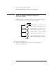

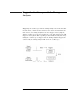
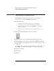
Table Of Contents
- A Quick Tour
- Before You Begin
- Introduction to Timing Analysis: Trigger on an Edge
- Verify Pulse Widths
- Introduction to State Analysis: Trigger on an Event
- Trigger on a Sequence of Events
- Trigger on a 4 Bit Serial Pattern
- Trigger the Oscilloscope with the Timing Analyzer
- Load the RESET Configuration File
- Connect the Oscilloscope Probe and Turn the Glitch On
- Get the Analog Waveform on the Display
- Set Up the Timing Analyzer
- Set Up the Timing Analyzer to Trigger on the Glitch
- Tell the Oscilloscope When to Trigger
- Set Up the Analyzer to Arm the Oscilloscope
- Run the Timing Analyzer and Oscilloscope
- Add the Analog Waveform to the Timing Waveform
- Turn the Glitch Off
- Save Your Work
- Lesson Summary
- Using the Pattern Generator
- Load the RESET Configuration File
- Connect the Pattern Generator
- Set Up the Timing Analyzer
- Set Up the Bus Labels
- Define the Trigger Conditions: Trigger on a 1
- Set Up the Pattern Generator
- Program the Pattern Generator Output
- Start the Pattern Generator and View the Walking Ones Pattern
- Stop the Pattern Generator
- Save Your Work
- Lesson Summary
- Setting the Jumpers
- About the Credit Card Board
98
Trigger the Oscilloscope with the Timing
Analyzer
Triggering the oscilloscope with the timing analyzer is an “intermodule
measurement,” which means it involves more than one instrument. In
this exercise, the timing analyzer is used to trigger on the symptom,
and the oscilloscope is used to monitor the cause. The symptom we will
trigger on is the glitch. This capturing of data simultaneously is done by
telling the oscilloscope to trigger after the timing analyzer triggers. In
other words, the timing analyzer will “arm” the oscilloscope.