
Installation guide
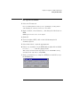
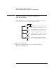
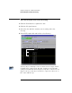

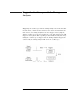
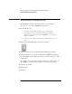
Table Of Contents
- A Quick Tour
- Before You Begin
- Introduction to Timing Analysis: Trigger on an Edge
- Verify Pulse Widths
- Introduction to State Analysis: Trigger on an Event
- Trigger on a Sequence of Events
- Trigger on a 4 Bit Serial Pattern
- Trigger the Oscilloscope with the Timing Analyzer
- Load the RESET Configuration File
- Connect the Oscilloscope Probe and Turn the Glitch On
- Get the Analog Waveform on the Display
- Set Up the Timing Analyzer
- Set Up the Timing Analyzer to Trigger on the Glitch
- Tell the Oscilloscope When to Trigger
- Set Up the Analyzer to Arm the Oscilloscope
- Run the Timing Analyzer and Oscilloscope
- Add the Analog Waveform to the Timing Waveform
- Turn the Glitch Off
- Save Your Work
- Lesson Summary
- Using the Pattern Generator
- Load the RESET Configuration File
- Connect the Pattern Generator
- Set Up the Timing Analyzer
- Set Up the Bus Labels
- Define the Trigger Conditions: Trigger on a 1
- Set Up the Pattern Generator
- Program the Pattern Generator Output
- Start the Pattern Generator and View the Walking Ones Pattern
- Stop the Pattern Generator
- Save Your Work
- Lesson Summary
- Setting the Jumpers
- About the Credit Card Board
94
Chapter 7: Trigger on a 4 Bit Serial Pattern
Run the Analyzer and View the Listing
Run the Analyzer and View the Listing
1 Click the Run button to capture the data.
2 Click the Navigate button.
3 Select the slot with the analyzer you are using, and select
Listing...
4 Under BIT0, right-click and hold to select Binary.
You may only see 0 through -3 lines of data before the trigger, which
would show the serial pattern ‘101’. The analyzer saw the full 4-bit
serial pattern ‘0101’ but did not display enough lines of data before the
trigger to show you this. If you click Run a couple more times, the -4
line of data will show up.
This is the 4-bit serial
pattern.