
Installation guide
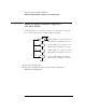
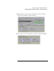
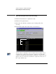

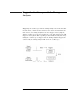
Table Of Contents
- A Quick Tour
- Before You Begin
- Introduction to Timing Analysis: Trigger on an Edge
- Verify Pulse Widths
- Introduction to State Analysis: Trigger on an Event
- Trigger on a Sequence of Events
- Trigger on a 4 Bit Serial Pattern
- Trigger the Oscilloscope with the Timing Analyzer
- Load the RESET Configuration File
- Connect the Oscilloscope Probe and Turn the Glitch On
- Get the Analog Waveform on the Display
- Set Up the Timing Analyzer
- Set Up the Timing Analyzer to Trigger on the Glitch
- Tell the Oscilloscope When to Trigger
- Set Up the Analyzer to Arm the Oscilloscope
- Run the Timing Analyzer and Oscilloscope
- Add the Analog Waveform to the Timing Waveform
- Turn the Glitch Off
- Save Your Work
- Lesson Summary
- Using the Pattern Generator
- Load the RESET Configuration File
- Connect the Pattern Generator
- Set Up the Timing Analyzer
- Set Up the Bus Labels
- Define the Trigger Conditions: Trigger on a 1
- Set Up the Pattern Generator
- Program the Pattern Generator Output
- Start the Pattern Generator and View the Walking Ones Pattern
- Stop the Pattern Generator
- Save Your Work
- Lesson Summary
- Setting the Jumpers
- About the Credit Card Board
91
Chapter 7: Trigger on a 4 Bit Serial Pattern
Set Up the Bus Labels
Set Up the Bus Labels
1 Select the Format tab.
Now you will organize the data you are capturing by creating a label
and assigning the channels of interest to that label.
2 Click on Label1, select Rename..., and change the label name to
BIT0.
BIT0 represents the source of the signal.
3 Click OK.
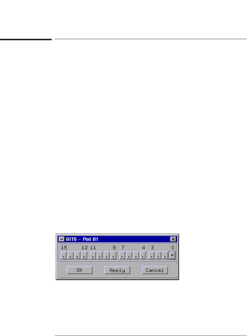
4 To the far right of BIT0, click on the field showing the 16
channels of pod 1.
5 Select Individual... from the pop-up menu.
6 If there are asterisks ‘*’ in the BIT0 window, right-click and hold
to select ‘................’ from the pop-up menu.
This changes the bits from being assigned to the label BIT0 to being
unassigned. We only want to assign BIT0.
7 Click on channel zero to assign it to BIT0, then click OK to close
the BIT0 window.