
Installation guide

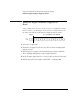
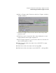
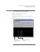
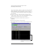
Table Of Contents
- A Quick Tour
- Before You Begin
- Introduction to Timing Analysis: Trigger on an Edge
- Verify Pulse Widths
- Introduction to State Analysis: Trigger on an Event
- Trigger on a Sequence of Events
- Trigger on a 4 Bit Serial Pattern
- Trigger the Oscilloscope with the Timing Analyzer
- Load the RESET Configuration File
- Connect the Oscilloscope Probe and Turn the Glitch On
- Get the Analog Waveform on the Display
- Set Up the Timing Analyzer
- Set Up the Timing Analyzer to Trigger on the Glitch
- Tell the Oscilloscope When to Trigger
- Set Up the Analyzer to Arm the Oscilloscope
- Run the Timing Analyzer and Oscilloscope
- Add the Analog Waveform to the Timing Waveform
- Turn the Glitch Off
- Save Your Work
- Lesson Summary
- Using the Pattern Generator
- Load the RESET Configuration File
- Connect the Pattern Generator
- Set Up the Timing Analyzer
- Set Up the Bus Labels
- Define the Trigger Conditions: Trigger on a 1
- Set Up the Pattern Generator
- Program the Pattern Generator Output
- Start the Pattern Generator and View the Walking Ones Pattern
- Stop the Pattern Generator
- Save Your Work
- Lesson Summary
- Setting the Jumpers
- About the Credit Card Board
65
Chapter 5: Introduction to State Analysis: Trigger on an Event
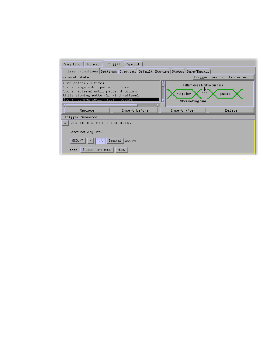
Define the Trigger Conditions: Trigger on an Event
6 Click on Trigger and fill memory and select Trigger, and then
Trigger and goto.
7 Under the Trigger Functions tab, click on ‘Store range until
pattern occurs’.
8 Click Insert after to insert the ‘Store range until patter occurs’
trigger function after Trigger Sequence 1.
9 In the Trigger Sequence 2, click on Hex and select Decimal. Do
this for both instances of Hex.
10 Click in the first field to the right of Store SCOUNT In range,
and type 004.
11 Click in the field to the right of 004 and type 009.
12 Click in the field to the right of until SCOUNT =, and type 010.