
Installation guide

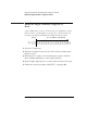
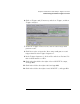
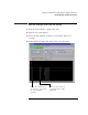
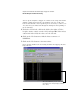
Table Of Contents
- A Quick Tour
- Before You Begin
- Introduction to Timing Analysis: Trigger on an Edge
- Verify Pulse Widths
- Introduction to State Analysis: Trigger on an Event
- Trigger on a Sequence of Events
- Trigger on a 4 Bit Serial Pattern
- Trigger the Oscilloscope with the Timing Analyzer
- Load the RESET Configuration File
- Connect the Oscilloscope Probe and Turn the Glitch On
- Get the Analog Waveform on the Display
- Set Up the Timing Analyzer
- Set Up the Timing Analyzer to Trigger on the Glitch
- Tell the Oscilloscope When to Trigger
- Set Up the Analyzer to Arm the Oscilloscope
- Run the Timing Analyzer and Oscilloscope
- Add the Analog Waveform to the Timing Waveform
- Turn the Glitch Off
- Save Your Work
- Lesson Summary
- Using the Pattern Generator
- Load the RESET Configuration File
- Connect the Pattern Generator
- Set Up the Timing Analyzer
- Set Up the Bus Labels
- Define the Trigger Conditions: Trigger on a 1
- Set Up the Pattern Generator
- Program the Pattern Generator Output
- Start the Pattern Generator and View the Walking Ones Pattern
- Stop the Pattern Generator
- Save Your Work
- Lesson Summary
- Setting the Jumpers
- About the Credit Card Board
64
Chapter 5: Introduction to State Analysis: Trigger on an Event
Define the Trigger Conditions: Trigger on an Event
Define the Trigger Conditions: Trigger on an
Event
A state analyzer has “sequence levels” that let you qualify data storage.
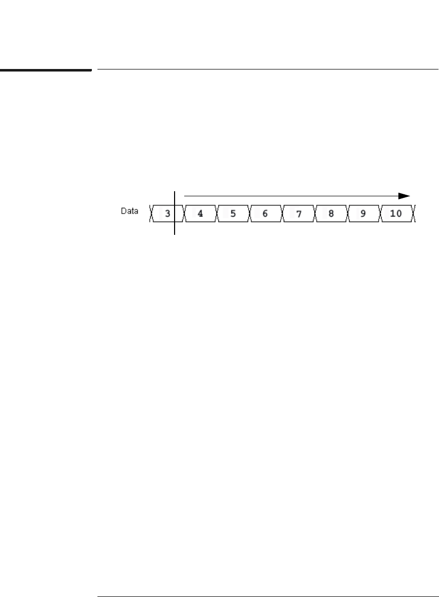
In this exercise, you will trigger on the pattern 3, and then only store
the range 4-9 and pattern 10 until the analyzers memory is full.
1 Select the Trigger tab.
2 Under the Trigger Functions tab, click on ‘Store nothing until
pattern occurs’.
3 Click Replace to replace the default trigger sequence with the
‘Store nothing until patter occurs’ trigger function.
4 In the Trigger Sequence box 1, click on Hex and select Decimal.
5 Click in the field to the right of SCOUNT =, and type 003.
Trigger
Store RANGE4-9 or EVENT10