
Installation guide
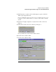
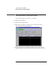
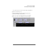

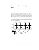
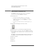
Table Of Contents
- A Quick Tour
- Before You Begin
- Introduction to Timing Analysis: Trigger on an Edge
- Verify Pulse Widths
- Introduction to State Analysis: Trigger on an Event
- Trigger on a Sequence of Events
- Trigger on a 4 Bit Serial Pattern
- Trigger the Oscilloscope with the Timing Analyzer
- Load the RESET Configuration File
- Connect the Oscilloscope Probe and Turn the Glitch On
- Get the Analog Waveform on the Display
- Set Up the Timing Analyzer
- Set Up the Timing Analyzer to Trigger on the Glitch
- Tell the Oscilloscope When to Trigger
- Set Up the Analyzer to Arm the Oscilloscope
- Run the Timing Analyzer and Oscilloscope
- Add the Analog Waveform to the Timing Waveform
- Turn the Glitch Off
- Save Your Work
- Lesson Summary
- Using the Pattern Generator
- Load the RESET Configuration File
- Connect the Pattern Generator
- Set Up the Timing Analyzer
- Set Up the Bus Labels
- Define the Trigger Conditions: Trigger on a 1
- Set Up the Pattern Generator
- Program the Pattern Generator Output
- Start the Pattern Generator and View the Walking Ones Pattern
- Stop the Pattern Generator
- Save Your Work
- Lesson Summary
- Setting the Jumpers
- About the Credit Card Board
58
Introduction to State Analysis: Trigger on an
Event
If you’ve never used a state analyzer, you may think it’s a complex
instrument that would take much time to master. Actually, the state
analyzer is not any more difficult to understand than a timing analyzer.
The major difference between a timing analyzer and a state analyzer is
the source of the sample clock. While the timing analyzer samples at
regular intervals using the internal clock, the state analyzer samples
when you tell it to using an external clock. Each time the state analyzer
receives a state clock pulse, the analyzer samples and stores the logic
state of the system under test.
DATA
1. AA
2. 01
3. 2F
4. 3B
AA 01 2F 3B
DATA
CLOCK
Sample Sample Sample Sample