
Installation guide
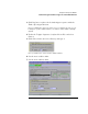
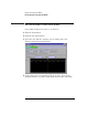

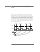
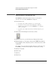
Table Of Contents
- A Quick Tour
- Before You Begin
- Introduction to Timing Analysis: Trigger on an Edge
- Verify Pulse Widths
- Introduction to State Analysis: Trigger on an Event
- Trigger on a Sequence of Events
- Trigger on a 4 Bit Serial Pattern
- Trigger the Oscilloscope with the Timing Analyzer
- Load the RESET Configuration File
- Connect the Oscilloscope Probe and Turn the Glitch On
- Get the Analog Waveform on the Display
- Set Up the Timing Analyzer
- Set Up the Timing Analyzer to Trigger on the Glitch
- Tell the Oscilloscope When to Trigger
- Set Up the Analyzer to Arm the Oscilloscope
- Run the Timing Analyzer and Oscilloscope
- Add the Analog Waveform to the Timing Waveform
- Turn the Glitch Off
- Save Your Work
- Lesson Summary
- Using the Pattern Generator
- Load the RESET Configuration File
- Connect the Pattern Generator
- Set Up the Timing Analyzer
- Set Up the Bus Labels
- Define the Trigger Conditions: Trigger on a 1
- Set Up the Pattern Generator
- Program the Pattern Generator Output
- Start the Pattern Generator and View the Walking Ones Pattern
- Stop the Pattern Generator
- Save Your Work
- Lesson Summary
- Setting the Jumpers
- About the Credit Card Board
51
Chapter 4: Verify Pulse Widths
Define the Trigger Conditions: Trigger on a Pulse Width Violation
3 Click Replace to replace the default trigger sequence with the
‘Find edge’ trigger function.
Next you will define what you want to use for a trigger. Because we are
looking for a pulse width violation, we will check the width of all high
signals.
4 Under the Trigger Sequence 1, right-click on Hex and select
Binary.
5 Click in the field to the left of Binary and type 1.
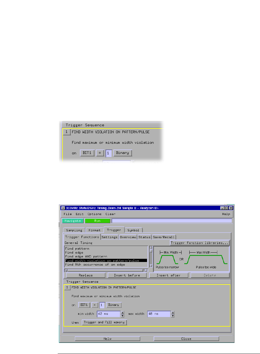
Now you will set the values for the width violation.
6 Set the max width to 48ns.
7 Set the min width to 42ns.