
Installation guide
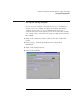
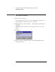
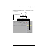
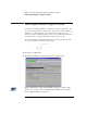
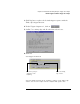
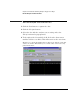
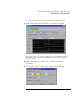
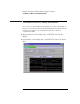

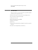
Table Of Contents
- A Quick Tour
- Before You Begin
- Introduction to Timing Analysis: Trigger on an Edge
- Verify Pulse Widths
- Introduction to State Analysis: Trigger on an Event
- Trigger on a Sequence of Events
- Trigger on a 4 Bit Serial Pattern
- Trigger the Oscilloscope with the Timing Analyzer
- Load the RESET Configuration File
- Connect the Oscilloscope Probe and Turn the Glitch On
- Get the Analog Waveform on the Display
- Set Up the Timing Analyzer
- Set Up the Timing Analyzer to Trigger on the Glitch
- Tell the Oscilloscope When to Trigger
- Set Up the Analyzer to Arm the Oscilloscope
- Run the Timing Analyzer and Oscilloscope
- Add the Analog Waveform to the Timing Waveform
- Turn the Glitch Off
- Save Your Work
- Lesson Summary
- Using the Pattern Generator
- Load the RESET Configuration File
- Connect the Pattern Generator
- Set Up the Timing Analyzer
- Set Up the Bus Labels
- Define the Trigger Conditions: Trigger on a 1
- Set Up the Pattern Generator
- Program the Pattern Generator Output
- Start the Pattern Generator and View the Walking Ones Pattern
- Stop the Pattern Generator
- Save Your Work
- Lesson Summary
- Setting the Jumpers
- About the Credit Card Board
35
Chapter 3: Introduction to Timing Analysis: Trigger on an Edge
Define Trigger Conditions: Trigger on an Edge
3 Click Replace to replace the default trigger sequence with the
‘Find edge’ trigger function.
4 Under Trigger Sequence 1, click on .
5 Set Bit 7 as a rising edge and all other bits as don’t care.
6 Click OK.
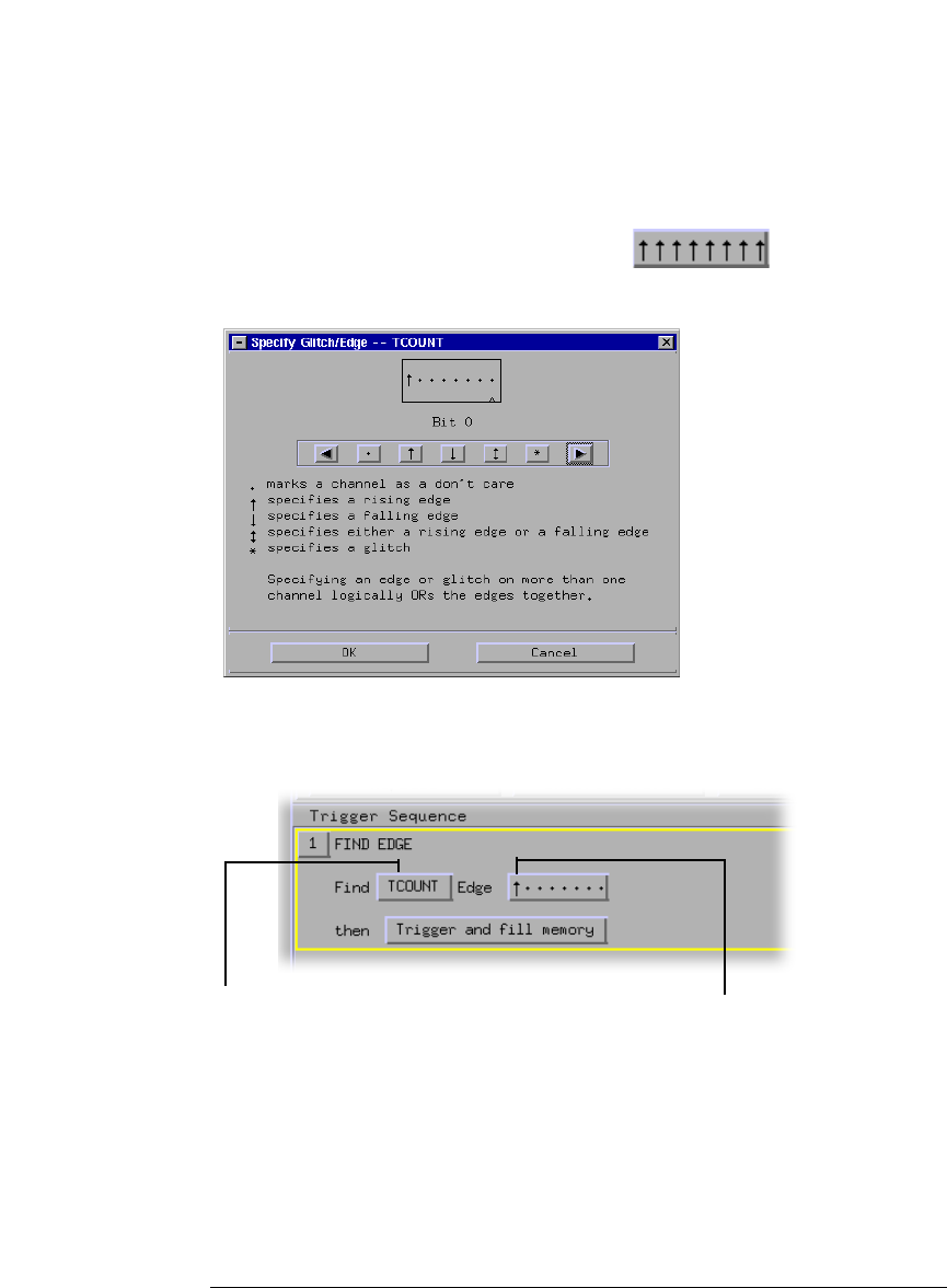
Your trigger should read:
You have finished setting up the analyzer to trigger on the rising edge
of bit 7. You are now ready to run the analyzer and capture data.
This is the rising
edge of bit 7.
This is the group of
channels you are
analyzing.