
Installation guide


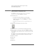
Table Of Contents
- A Quick Tour
- Before You Begin
- Introduction to Timing Analysis: Trigger on an Edge
- Verify Pulse Widths
- Introduction to State Analysis: Trigger on an Event
- Trigger on a Sequence of Events
- Trigger on a 4 Bit Serial Pattern
- Trigger the Oscilloscope with the Timing Analyzer
- Load the RESET Configuration File
- Connect the Oscilloscope Probe and Turn the Glitch On
- Get the Analog Waveform on the Display
- Set Up the Timing Analyzer
- Set Up the Timing Analyzer to Trigger on the Glitch
- Tell the Oscilloscope When to Trigger
- Set Up the Analyzer to Arm the Oscilloscope
- Run the Timing Analyzer and Oscilloscope
- Add the Analog Waveform to the Timing Waveform
- Turn the Glitch Off
- Save Your Work
- Lesson Summary
- Using the Pattern Generator
- Load the RESET Configuration File
- Connect the Pattern Generator
- Set Up the Timing Analyzer
- Set Up the Bus Labels
- Define the Trigger Conditions: Trigger on a 1
- Set Up the Pattern Generator
- Program the Pattern Generator Output
- Start the Pattern Generator and View the Walking Ones Pattern
- Stop the Pattern Generator
- Save Your Work
- Lesson Summary
- Setting the Jumpers
- About the Credit Card Board
23
Chapter 2: Before You Begin
2 Set the jumpers on the credit card board as shown below.
Chapter 10 “Setting the Jumpers” for more information on the jumper
settings of J5 on the credit card board.
Turn the Power On
3 Turn on the Agilent 16600/700 logic analysis system by flipping
the power switch to ON.
Activate the Analyzer
4 Once the Main System window comes up on your monitor, click
the analyzer you have connected to the credit card board.
5 Select Setup... from the pop-up menu to activate that
instrument.
If you should ever connect the credit card board to a different
analyzer, you must repeat steps 4 through 5 before going on to step 8.