
Installation guide


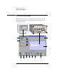
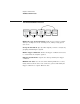

Table Of Contents
- A Quick Tour
- Before You Begin
- Introduction to Timing Analysis: Trigger on an Edge
- Verify Pulse Widths
- Introduction to State Analysis: Trigger on an Event
- Trigger on a Sequence of Events
- Trigger on a 4 Bit Serial Pattern
- Trigger the Oscilloscope with the Timing Analyzer
- Load the RESET Configuration File
- Connect the Oscilloscope Probe and Turn the Glitch On
- Get the Analog Waveform on the Display
- Set Up the Timing Analyzer
- Set Up the Timing Analyzer to Trigger on the Glitch
- Tell the Oscilloscope When to Trigger
- Set Up the Analyzer to Arm the Oscilloscope
- Run the Timing Analyzer and Oscilloscope
- Add the Analog Waveform to the Timing Waveform
- Turn the Glitch Off
- Save Your Work
- Lesson Summary
- Using the Pattern Generator
- Load the RESET Configuration File
- Connect the Pattern Generator
- Set Up the Timing Analyzer
- Set Up the Bus Labels
- Define the Trigger Conditions: Trigger on a 1
- Set Up the Pattern Generator
- Program the Pattern Generator Output
- Start the Pattern Generator and View the Walking Ones Pattern
- Stop the Pattern Generator
- Save Your Work
- Lesson Summary
- Setting the Jumpers
- About the Credit Card Board

17
Chapter 1: A Quick Tour
The Main System Window
.
A Navigate is used to access instruments and the windows such as Setup...,
Waveform..., Listing..., and the Source Viewer... window.
B Instrument icons are used to access the setup window for that particular
instrument. Each icon represents the instrument installed.
C Setup Assistant is used to start the automated process of setting up a
microprocessor analysis measurement.
D File Manager is used to perform the common tasks of loading or saving
measurement configurations. The File Manager has all the standard functionality
for performing operations on files and directories on both the flexible and hard
disk drives.
E Workspa ce shows a complete graphical representation of the tools and how
they are connected for your measurement configuration.
F Inter-Module shows a graphical representation of the arming sequence
between measurement modules, and any external trigger connections to a target
system or other instruments.
G Run Status is used to monitor the run function, and feed back information on
the progress of elements such as pre-store, trigger status, and post-store.
H System Admin is used to setup system defaults, network configurations, and
perform maintenance on the operating system file set. If you are working in a
multi-user environment (Secure mode), you set up user accounts in this dialog.
I Help gives you access to the main help system for the frame and system level
operations.
J The status line displays instructions on how to use parts of the interface by
pointing and holding the mouse over the area of interest.
K The back panel of the logic analysis system and the placements of the
modules are graphically represented.