
Installation guide

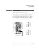


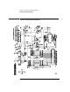
Table Of Contents
- A Quick Tour
- Before You Begin
- Introduction to Timing Analysis: Trigger on an Edge
- Verify Pulse Widths
- Introduction to State Analysis: Trigger on an Event
- Trigger on a Sequence of Events
- Trigger on a 4 Bit Serial Pattern
- Trigger the Oscilloscope with the Timing Analyzer
- Load the RESET Configuration File
- Connect the Oscilloscope Probe and Turn the Glitch On
- Get the Analog Waveform on the Display
- Set Up the Timing Analyzer
- Set Up the Timing Analyzer to Trigger on the Glitch
- Tell the Oscilloscope When to Trigger
- Set Up the Analyzer to Arm the Oscilloscope
- Run the Timing Analyzer and Oscilloscope
- Add the Analog Waveform to the Timing Waveform
- Turn the Glitch Off
- Save Your Work
- Lesson Summary
- Using the Pattern Generator
- Load the RESET Configuration File
- Connect the Pattern Generator
- Set Up the Timing Analyzer
- Set Up the Bus Labels
- Define the Trigger Conditions: Trigger on a 1
- Set Up the Pattern Generator
- Program the Pattern Generator Output
- Start the Pattern Generator and View the Walking Ones Pattern
- Stop the Pattern Generator
- Save Your Work
- Lesson Summary
- Setting the Jumpers
- About the Credit Card Board

143
Chapter 11: About the Credit Card Board
Jumpers
respectively. When the CLK1 and CLK2 jumpers are set to OSC
(oscillator), the clock source for the state analyzer is the oscillator on
the credit card board (Y1). When the CLK1 and CLK2 jumpers are set
to P.G. (pattern generator), the clock source for the state analyzer is
bit D7 or strobe 2 of the pattern generator, depending on which pattern
generator pod is connected to J4.
Jumpers
The jumpers are used to turn the glitch on and off and to select the
sources for state clocks 1 (CLK1) and 2 (CLK2).
Glitch
When the GLITCH jumper is set to OFF, the waveform on D7 of J1 and
J2 is the most significant bit of the counter. When this jumper is set to
ON, a glitch appears on D7 and the waveform no longer represents the
most significant bit of the counter. The glitch always appears on the
test point labeled GLITCH, regardless of the position of this jumper.
CLK1
The CLK1 jumper selects the source of state clock 1. If you choose OSC
(the default), the source of the clock will be the oscillator on the
training board. If you choose P.G., the source of the clock will be Strobe
2 or D7 of the pattern generator, depending on which pattern
generator pod you have connected to the credit card board.
CLK2
The CLK2 jumper selects the source of state clock 2 for the Agilent
16540A used in an Agilent 16600/700 system. If you choose OSC, the
source of the clock will be the oscillator on the credit card board. If you
choose P.G. (the default), the source of the clock will be Strobe 2 or D7
of the pattern generator, depending on which pattern generator pod
you have connected to the credit card board.