
Installation guide

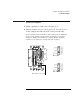


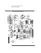
Table Of Contents
- A Quick Tour
- Before You Begin
- Introduction to Timing Analysis: Trigger on an Edge
- Verify Pulse Widths
- Introduction to State Analysis: Trigger on an Event
- Trigger on a Sequence of Events
- Trigger on a 4 Bit Serial Pattern
- Trigger the Oscilloscope with the Timing Analyzer
- Load the RESET Configuration File
- Connect the Oscilloscope Probe and Turn the Glitch On
- Get the Analog Waveform on the Display
- Set Up the Timing Analyzer
- Set Up the Timing Analyzer to Trigger on the Glitch
- Tell the Oscilloscope When to Trigger
- Set Up the Analyzer to Arm the Oscilloscope
- Run the Timing Analyzer and Oscilloscope
- Add the Analog Waveform to the Timing Waveform
- Turn the Glitch Off
- Save Your Work
- Lesson Summary
- Using the Pattern Generator
- Load the RESET Configuration File
- Connect the Pattern Generator
- Set Up the Timing Analyzer
- Set Up the Bus Labels
- Define the Trigger Conditions: Trigger on a 1
- Set Up the Pattern Generator
- Program the Pattern Generator Output
- Start the Pattern Generator and View the Walking Ones Pattern
- Stop the Pattern Generator
- Save Your Work
- Lesson Summary
- Setting the Jumpers
- About the Credit Card Board

142
About the Credit Card Board
The credit card board helps you learn the basics of Agilent Logic
Analyzers. The following reference information is provided for those
who want to know more about how the credit card board works.
Power Source
The credit card board is powered by the +5 V supplied by the logic
analyzer pods, so a logic analyzer pod must be connected to either J1
or J2 of the credit card board in order for the board to work. If only J2
is connected, it must be connected to the logic analyzer through a
termination adapter (Agilent part number 01650-63203).
CAUTION: If the termination adapter part number is Agilent 01650-63201, the CLK2
jumper must be set to P.G. to avoid connecting the output of the oscillator to
+5 V and eventually damaging the oscillator.
If J1 is connected, the termination adapter is not required because J1 is
terminated on the board by Z1 and Z2.
Circuit Description
The credit card board uses an 8-bit ripple counter running at 32 MHz to
produce transitions on the lower 8 bits of a logic analyzer pod. The
upper eight bits can be connected to the pattern generator through
connector J4.
For state analysis, you can clock the state analyzer using the oscillator
on the credit card board (reference designator Y1) or using a pattern
generator in an Agilent16600/700 system. The sources for clocks 1 and
2 are selected by the positions of jumpers CLK1 and CLK2,