
Installation guide


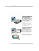

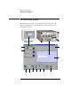
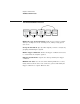

Table Of Contents
- A Quick Tour
- Before You Begin
- Introduction to Timing Analysis: Trigger on an Edge
- Verify Pulse Widths
- Introduction to State Analysis: Trigger on an Event
- Trigger on a Sequence of Events
- Trigger on a 4 Bit Serial Pattern
- Trigger the Oscilloscope with the Timing Analyzer
- Load the RESET Configuration File
- Connect the Oscilloscope Probe and Turn the Glitch On
- Get the Analog Waveform on the Display
- Set Up the Timing Analyzer
- Set Up the Timing Analyzer to Trigger on the Glitch
- Tell the Oscilloscope When to Trigger
- Set Up the Analyzer to Arm the Oscilloscope
- Run the Timing Analyzer and Oscilloscope
- Add the Analog Waveform to the Timing Waveform
- Turn the Glitch Off
- Save Your Work
- Lesson Summary
- Using the Pattern Generator
- Load the RESET Configuration File
- Connect the Pattern Generator
- Set Up the Timing Analyzer
- Set Up the Bus Labels
- Define the Trigger Conditions: Trigger on a 1
- Set Up the Pattern Generator
- Program the Pattern Generator Output
- Start the Pattern Generator and View the Walking Ones Pattern
- Stop the Pattern Generator
- Save Your Work
- Lesson Summary
- Setting the Jumpers
- About the Credit Card Board

14
A Quick Tour
Welcome to your new logic analysis system. You have either the
Agilent 16600A-Series or the Agilent 16700A-Series logic analysis
system. This quick tour applies to both series.
Your Agilent 16600A-Series
Logic Analysis System
The Agilent 16600A-Series logic
analysis system frame includes an
embedded logic analyzer
acquisition module. One modular
slot is also available for
integration of an oscilloscope,
pattern generator, or another
logic analyzer. There is also one
emulation module slot.
Your Agilent 16700A-Series
Logic Analysis System
The Agilent 16700A-Series logic
analysis system frame has five
slots for measurement modules,
and two dedicated emulation
module slots.
The Agilent 16702A-Series logic
analysis system also includes a
built in flat-panel display and
keyboard.