Installation Guide Publication number 16700-97023 November 2002 For Safety information and Regulatory information, see the pages behind the index.
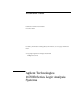
Installation at a Glance 16700B Overview 16700B Mainframe If ordered: Monitor Monitor Cable Monitor Power Cable Power Cable Keyboard & Mouse Training Board & Kit Additional Connections 16701A/B Expander Frame Printer & Cable External Disk Drive & Cable (Data Drive - Option 008) (Boot Drive - Option 009) 2
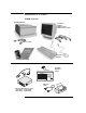
16702B Overview Training Board & Kit 16702B Mainframe Keyboard & Mouse Power Cable Additional Connections Orderable: Monitor Monitor Cable Monitor Power Cable External Disk Drive & Cable (Data Drive - Option 008) (Boot Drive - Option 009) Printer & Cable 16701A/B Expander Frame 3
Contents Installation at a Glance 1 General Information 9 To locate information on using the logic analyzer 10 To locate specifications and characteristics 11 To create a backup file of your system settings and license passwords To reload system settings and license passwords 15 2 Connecting and Configuring Hardware 13 17 To connect the mouse, keyboard, and monitor 18 To configure a monitor for the 16700B 19 To configure an optional monitor for the 16702B 21 To change monitors (16700B or 16702B) 2
Contents Software Requirements 46 16517/18A Logic Analyzer (2-card module) 47 16517/18A Logic Analyzer (3-card module) 48 16517/18A Logic Analyzer (4-card module) 49 16517/18A Logic Analyzer (5-card module) 50 16557D Logic Analyzer (1-card module) 50 16557D Logic Analyzer (2-card module) 51 16557D Logic Analyzer (3-card module) 52 16557D Logic Analyzer (3-card module) 53 16557D Logic Analyzer (5-card module) 54 16710/11/12A Logic Analyzer (1-card module) 55 16710/11/12A Logic Analyzer (2-card module) 56 16
Contents Measurement Modules 71 16533/34A Oscilloscope Module (single or multi-card modules) 5 Installing Pattern Generator Measurement Modules Software Requirements 88 16522A Pattern Generator (1-card module) 16522A Pattern Generator (2-card module) 16522A Pattern Generator (3-card module) 16522A Pattern Generator (4-card module) 16522A Pattern Generator (5-card module) 16720A Pattern Generator (1-card module) 16720A Pattern Generator (2-card module) 16720A Pattern Generator (3-card module) 16720A Pat
Contents 100-pin Differential Probe (E5379A for analyzers with 90-pin pod connectors) 107 38-pin Single-ended Probe (E5380A for analyzers with 90-pin pod connectors) 108 Half-channel Adapter (E5386A) 109 Single-ended Flying Lead Probe Set (E5382A) 110 Soft Touch Probes (E5387A and E5390A for analyzers with 90-pin pod connectors) 111 7 Troubleshooting 113 To run self-tests 114 To execute disaster recovery procedures 8 115
1 General Information 9
Chapter 1: General Information To locate information on using the logic analyzer To locate information on using the logic analyzer Go to on-line help for information on using your logic analyzer. A pdf file of the on-line help is on the CD that came with your system if you want to print it out. 1 Select Help in the upper right corner of the screen and then select On Main System. 2 Select the task you need information about. .
Chapter 1: General Information To locate specifications and characteristics To locate specifications and characteristics The specifications and characteristics for your instrument and measurement module are in the on-line Help. 1 Select Help in the upper right corner of the screen and then select On Main System. 2 Select Using Measurement Tools and then select your instrument or measurement module from the list.
Chapter 1: General Information To locate specifications and characteristics 3 Under Interface Reference, select Specifications and Characteristics.
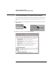
Chapter 1: General Information To create a backup file of your system settings and license passwords To create a backup file of your system settings and license passwords By saving your system settings to a flexible disk or a mounted directory, you create a backup file that can be used to quickly setup systems or to restore current system settings in case of problems. 1 Insert a flexible disk or set up a mounted directory. 2 Select the Tools icon from the menu bar.
Chapter 1: General Information To create a backup file of your system settings and license passwords 4 Select Flexible Disk or a Mounted Directory and then select OK.
Chapter 1: General Information To reload system settings and license passwords To reload system settings and license passwords 1 Insert the flexible disk or set up a mounted directory. 2 Select the Tools icon from the menu bar. 3 Go to the Admin tab and select Load.
Chapter 1: General Information To reload system settings and license passwords 4 Select Flexible Disk or Mounted Directory and select OK. If an item is not valid, or was not initially saved to the file, the selection will be grayed out in the interface. Also, if no file extension is added, a ‘.set’ extension is automatically added for you.
2 Connecting and Configuring Hardware 17
Chapter 2: Connecting and Configuring Hardware To connect the mouse, keyboard, and monitor To connect the mouse, keyboard, and monitor The 16700B must have the system mouse and keyboard connected for the system to boot up properly. Once enabled on the LAN, the system can be operated remotely without a keyboard or mouse. Use of a monitor is optional for the 16700B and 16702B. 1 Connect the mouse and keyboard to the back of the 16700B or 16702B.
Chapter 2: Connecting and Configuring Hardware To configure a monitor for the 16700B 4 Allow a minimum of 5 cm spacing between instruments for proper cooling. 5cm 5cm 16700B 5cm 5cm 16702B To configure a monitor for the 16700B If you ordered the optional monitor with your logic analyzer, the monitor resolution setting is pre-configured for 1280 x 1024 at the factory. Use this procedure if you wish to configure an external monitor other than the optional monitor orderable with the 16700B.
Chapter 2: Connecting and Configuring Hardware To configure a monitor for the 16700B 3 Immediately press the TAB key. Press once per second for approximately 30 seconds. The monitor display will change on the screen every few seconds as the system cycles through the monitor resolution choices. 4 Press ENTER when you see a clear image to select your monitor choice and type ‘Y” to confirm.
Chapter 2: Connecting and Configuring Hardware To configure an optional monitor for the 16702B To configure an optional monitor for the 16702B The internal LCD display is pre-configured for 800 x 600 at the factory. Use this procedure if you wish to configure an external monitor or change the monitor setting to a different resolution. 1 Connect your monitor to the logic analysis system as shown on page 18. 2 Turn on power to the monitor and then to the logic analysis system.
Chapter 2: Connecting and Configuring Hardware To change monitors (16700B or 16702B) 4 Press ENTER when you see a clear image to select your monitor choice and type ‘Y” to confirm. Clear Images To change monitors (16700B or 16702B) Any time you change monitors you will need to re-configure the new monitor. Follow the instructions beginning with step one on page 19 if you have a 16700B or page 21 if you have a 16702B. To connect to LAN 1 Connect the LAN cable to the back of the16700B or 16702B.
Chapter 2: Connecting and Configuring Hardware To connect to LAN 2 Go to the Help menu and select On Main System. 3 In the Help window select System Administration and then select Configuring the Network. Follow the instructions on configuring the network.
Chapter 2: Connecting and Configuring Hardware To connect a printer To connect a printer 1 Connect the printer cable to the back of your 16700B or 16702B. 2 Select the Tools icon from the menu bar. 3 Go to the Admin. tab and select Printers.
Chapter 2: Connecting and Configuring Hardware To connect a printer 4 If you are connecting a local printer, select Local, select your printer type, select OK, and then Close. (Your printer) 5 If you are connecting a network printer, select Network, enter the printer name, server address, select type, select OK, and then Close.
Chapter 2: Connecting and Configuring Hardware To connect an external data drive (option 008) To connect an external data drive (option 008) 1 Power up the data drive. 2 Set the address. a Unlock the data drive carrier. Wait until the drive stops spinning and a “u” is displayed as shown. CAUTION: Damage could result to the data drive if it is removed from the carrier while the number is flashing. b Remove the data drive from the carrier.
Chapter 2: Connecting and Configuring Hardware To connect an external data drive (option 008) c Set the external data drive address to 3 or 4 using the alignment tool supplied with the drive. The rotating switch is located inside the carrier. d Insert the disk drive into the carrier and lock it into place. 3 Power down the data drive.
Chapter 2: Connecting and Configuring Hardware To connect an external data drive (option 008) 4 Connect the data drive to the SCSI-II port. 16700B or 16702B (68 pin) Termination Plug (68 pin) (50 pin) External Disk Drive Cable 5 Power up the data drive, then the monitor, and then the system (16700B or 16702B). 16700A 16700B or 16702B Power Busy 6 Mount the disk.
Chapter 2: Connecting and Configuring Hardware To connect an external data drive (option 008) b Go to the Admin. tab and select Mount External Disk. c Select SCSI Address to the same number set in step 2, then Mount, and Close.
Chapter 2: Connecting and Configuring Hardware To disconnect an external data drive (option 008) To disconnect an external data drive (option 008) It is important that you unmount the disk before turning the system off. 1 Select the Tools icon from the menu bar. 2 Select the Admin. tab, select Mount External Disk, select Unmount, and then Close.
Chapter 2: Connecting and Configuring Hardware To connect a removable boot drive (option 009) 3 Turn the power off on the system, then the monitor, and then the data drive. 16700A 16700B or 16702B Power Busy To connect a removable boot drive (option 009) 1 Power up the boot drive. 2 Set the address. a Unlock the boot drive carrier. Wait until the drive stops spinning and a “u” is displayed as shown.
Chapter 2: Connecting and Configuring Hardware To connect a removable boot drive (option 009) b Remove the boot drive from the carrier. c Set the external boot drive address to 6 using the alignment tool supplied with the drive. The rotating switch is located inside the carrier. d Insert the disk into the carrier drive and lock it into place.
Chapter 2: Connecting and Configuring Hardware To connect a removable boot drive (option 009) 3 Power down the boot drive. 4 Connect the boot drive to the SCSI-II port. 16700B or 16702B (68 pin) Termination Plug (68 pin) (50 pin) External Disk Drive Cable 5 Power up the boot drive, then the monitor, and then the system.
Chapter 2: Connecting and Configuring Hardware To disconnect a removable boot drive (option 009) To disconnect a removable boot drive (option 009) Turn the power off on the system, then the monitor, and then the boot drive. 16700A 16700B or 16702B Power Busy To install software When a system is shipped, the factory installs the current operating system and ordered processor support packages and tools. The latest software update is available at www.software.cos.agilent.com/16700.
Chapter 2: Connecting and Configuring Hardware To install software 2 Select the Software Install tab and then select Install. 3 Select the media type and select Apply. The resulting window will display software that can be loaded.
Chapter 2: Connecting and Configuring Hardware To install software 4 To load System Software, highlight it and select Install. 5 To load Additional Tools or Processor Support Software: a Double click to display the available packages. b Select one or more desired packages. A second click on a highlighted item will deselect it. c Select Install and the system will automatically reboot if it is required by the newly installed package.
Chapter 2: Connecting and Configuring Hardware To connect a 16701B expander frame To connect a 16701B expander frame 1 Install your measurement modules in the 16701B expander frame. Module installation instructions are on page 42. For information on specific measurement modules go to: Module Type Page Logic Analyzer Oscilloscope Pattern Generator 45 71 87 2 Connect either a 30 cm (12 inch) or 90 cm (36 inch) interconnect cable to the expander and system frames.
Chapter 2: Connecting and Configuring Hardware To connect multiple frames To connect multiple frames As many as eight 16700B’s and/or 16702B’s with expander frames may be connected together. To connect multiple frames you need to order 16700B option #012 and/or 16702B option #012. NOTE: The multiframe module requires software Rev. A.02.00.00 or higher. Agilent 16700B and 16702B logic analysis systems ordered with the multiframe option installed will have the current operating system software installed.
Chapter 2: Connecting and Configuring Hardware To connect multiple frames 7 Slide the bottom cover toward the rear of the instrument and away.. 8 Remove the cover plate.
Chapter 2: Connecting and Configuring Hardware To connect multiple frames 9 Insert the Multiframe Module with the cable attached. 16700e24.
Chapter 2: Connecting and Configuring Hardware To connect multiple frames 10 Connect the Multiframe Module cable to the connector on the bottom side of the Interface Board, insert the screws and reassemble the frame. 16700e25.cdr 11 Connect mainframe and expander frames together.The frame at the beginning of the series must have its INPUT port open and the last frame in the series must have its OUTPUT port open.
Chapter 2: Connecting and Configuring Hardware To install, remove, or replace measurement modules To install, remove, or replace measurement modules CAUTION: Electrostatic discharge can damage electronic components. Use grounded wrist straps and mats when performing any service to measurement modules. NOTE: Measurement modules with different model numbers may not be connected together in multi-card (Master/Expander) modules unless stated otherwise.
Chapter 2: Connecting and Configuring Hardware To install, remove, or replace measurement modules 4 If you are inserting more than one module, the tightening order is bottom module to top module. A single-module configuration can be installed in any available slot. Insert modules or filler panels. Remove filler panels. (Other modules or filler panels.) (Other modules or filler panels.) 5 Some modules require calibration if they are moved to a different slot.
Chapter 2: Connecting and Configuring Hardware To install, remove, or replace measurement modules 44
3 Installing Logic Analyzer Measurement Modules 45
Chapter 3: Installing Logic Analyzer Measurement Modules Software Requirements Software Requirements The following table gives you the software version required in your 16700A/B or 16702A/B mainframe for use with logic analyzer measurement modules. For software installation instructions go to page page 34. Model Number Software Version 16517/18A 16557D 16710/11/12A 16715/16/17A 16718/19A 16740/41/42A 16750/51/52A 16750/51/52B 16753/54/55/56A 16760A All versions All versions A.01.20.00 or higher A.01.40.
Chapter 3: Installing Logic Analyzer Measurement Modules 16517/18A Logic Analyzer (2-card module) 16517/18A Logic Analyzer (2-card module) The 16517A is the master card and the 16518A is the expander card. Connect the cards together in one of the two ways shown below. NOTE: Turn off the mainframe power before removing, replacing, or installing modules following the procedures on page 42.
Chapter 3: Installing Logic Analyzer Measurement Modules 16517/18A Logic Analyzer (3-card module) 16517/18A Logic Analyzer (3-card module) The 16517A is the master card and the 16518A cards are expander cards. Connect the cards together in one of the three ways shown below. NOTE: Turn off the mainframe power before removing, replacing, or installing modules following the procedures on page 42.
Chapter 3: Installing Logic Analyzer Measurement Modules 16517/18A Logic Analyzer (4-card module) 16517/18A Logic Analyzer (4-card module) The 16517A is the master card and the 16518A cards are expander cards. Connect the cards together in one of the two ways shown below. NOTE: Turn off the mainframe power before removing, replacing, or installing modules following the procedures on page 42.
Chapter 3: Installing Logic Analyzer Measurement Modules 16517/18A Logic Analyzer (5-card module) 16517/18A Logic Analyzer (5-card module) The 16517A is the master card and the 16518A cards are expander cards. Connect the cards together as shown below. NOTE: Turn off the mainframe power before removing, replacing, or installing modules following the procedures on page 42.
Chapter 3: Installing Logic Analyzer Measurement Modules 16557D Logic Analyzer (2-card module) 16557D Logic Analyzer (2-card module) Use two 2 x 25 cables and two 2 x 10 cables to connect the cards as shown. NOTE: Turn off the mainframe power before removing, replacing, or installing modules following the procedures on page 42.
Chapter 3: Installing Logic Analyzer Measurement Modules 16557D Logic Analyzer (3-card module) 16557D Logic Analyzer (3-card module) Use two 2 x 25 cables and three 2 x 10 cables to connect the cards as shown. NOTE: Turn off the mainframe power before removing, replacing, or installing modules following the procedures on page 42.
Chapter 3: Installing Logic Analyzer Measurement Modules 16557D Logic Analyzer (3-card module) 16557D Logic Analyzer (3-card module) Use two 2 x 25 cables and four 2 x 10 cables to connect the cards as shown. NOTE: Turn off the mainframe power before removing, replacing, or installing modules following the procedures on page 42.
Chapter 3: Installing Logic Analyzer Measurement Modules 16557D Logic Analyzer (5-card module) 16557D Logic Analyzer (5-card module) Use two 2 x 25 cables and five 2 x 10 cables to connect the cards as shown. NOTE: Turn off the mainframe power before removing, replacing, or installing modules following the procedures on page 42.
Chapter 3: Installing Logic Analyzer Measurement Modules 16710/11/12A Logic Analyzer (1-card module) 16710/11/12A Logic Analyzer (1-card module) A single 16710/11/12A logic analyzer module will have the 2 x 40 cable connected in the single-card configuration. NOTE: Turn off the mainframe power before removing, replacing, or installing modules following the procedures on page 42.
Chapter 3: Installing Logic Analyzer Measurement Modules 16710/11/12A Logic Analyzer (2-card module) 16710/11/12A Logic Analyzer (2-card module) Connect two modules as shown using two 2 x 25 cables and two 2 x 40 cables. NOTE: Turn off the mainframe power before removing, replacing, or installing modules following the procedures on page 42.
Chapter 3: Installing Logic Analyzer Measurement Modules 16715/16/17A, 16718/19A, 16740/41/42A, 16750/51/52A/B Logic Analyzer (1-card module) 16715/16/17A, 16718/19A, 16740/41/42A, 16750/51/52A/B Logic Analyzer (1-card module) Each card shipped stand-alone has the 2 x 10 cable connected in the singlecard module configuration. A single-card module can be installed in any available slot. NOTE: Turn off the mainframe power before removing, replacing, or installing modules following the procedures on page 42.
Chapter 3: Installing Logic Analyzer Measurement Modules 16715/16/17A, 16718/19A, 16740/41/42A, 16750/51/52A/B Logic Analyzer (2-card module) 16715/16/17A, 16718/19A, 16740/41/42A, 16750/51/52A/B Logic Analyzer (2-card module) Use two 2 x 10 cables and two 2 x 40 cables (in the accessory pouch) to connect the modules. NOTE: Turn off the mainframe power before removing, replacing, or installing modules following the procedures on page 42.
Chapter 3: Installing Logic Analyzer Measurement Modules 16715/16/17A, 16718/19A, 16740/41/42A, 16750/51/52A/B Logic Analyzer (3-card module) 16715/16/17A, 16718/19A, 16740/41/42A, 16750/51/52A/B Logic Analyzer (3-card module) Use three 2 x 10 cables and four 2 x 40 cables (in the accessory pouch) to connect the modules. NOTE: Turn off the mainframe power before removing, replacing, or installing modules following the procedures on page 42.
Chapter 3: Installing Logic Analyzer Measurement Modules 16715/16/17A, 16718/19A, 16740/41/42A, 16750/51/52A/B Logic Analyzer (4-card module) 16715/16/17A, 16718/19A, 16740/41/42A, 16750/51/52A/B Logic Analyzer (4-card module) Use four 2 x 10 cables and six 2 x 40 cables (in the accessory pouch) to connect the modules.
Chapter 3: Installing Logic Analyzer Measurement Modules 16715/16/17A, 16718/19A, 16740/41/42A, 16750/51/52A/B Logic Analyzer (5-card module) 16715/16/17A, 16718/19A, 16740/41/42A, 16750/51/52A/B Logic Analyzer (5-card module) Use five 2 x 10 cables and eight 2 x 40 cables (in the accessory pouch) to connect the modules NOTE: Turn off the mainframe power before removing, replacing, or installing modules following the procedures on page 42.
Chapter 3: Installing Logic Analyzer Measurement Modules 16753/54/55/56A Logic Analyzer (1-card module) 16753/54/55/56A Logic Analyzer (1-card module) Each card shipped stand-alone has the 2 x 15 cable connected in the singlecard module configuration. The 2 x 50 cables in the accessory pouch are not used. A single-card module can be installed in any available slot. NOTE: Turn off the mainframe power before removing, replacing, or installing modules following the procedures on page 42.
Chapter 3: Installing Logic Analyzer Measurement Modules 16753/54/55/56A Logic Analyzer (2-card module) 16753/54/55/56A Logic Analyzer (2-card module) Use two 2 x 15 cables and two 2 x 50 cables (in the accessory pouch) to connect the modules. NOTE: Turn off the mainframe power before removing, replacing, or installing modules following the procedures on page 42. NOTE: Measurement modules with different model numbers can be mixed in multicard modules.
Chapter 3: Installing Logic Analyzer Measurement Modules 16753/54/55/56A Logic Analyzer (3-card module) 16753/54/55/56A Logic Analyzer (3-card module) Use three 2 x 15 cables and four 2 x 50 cables (in the accessory pouch) to connect the modules. NOTE: Turn off the mainframe power before removing, replacing, or installing modules following the procedures on page 42. NOTE: Measurement modules with different model numbers can be mixed in multicard modules.
Chapter 3: Installing Logic Analyzer Measurement Modules 16753/54/55/56A Logic Analyzer (4-card module) 16753/54/55/56A Logic Analyzer (4-card module) Use four 2 x 15 cables and six 2 x 50 cables (in the accessory pouch) to connect the modules. NOTE: Turn off the mainframe power before removing, replacing, or installing modules following the procedures on page 42 NOTE: Measurement modules with different model numbers can be mixed in multicard modules.
Chapter 3: Installing Logic Analyzer Measurement Modules 16753/54/55/56A Logic Analyzer (5-card module) 16753/54/55/56A Logic Analyzer (5-card module) Use five 2 x 15 cables and eight 2 x 50 cables (in the accessory pouch) to connect the modules NOTE: Turn off the mainframe power before removing, replacing, or installing modules following the procedures on page 42. NOTE: Measurement modules with different model numbers can be mixed in multicard modules.
Chapter 3: Installing Logic Analyzer Measurement Modules 16760A Logic Analyzer (1-card module) 16760A Logic Analyzer (1-card module) A single 16760A logic analyzer module will have the 2 x 10 cable connected in the single-card configuration. NOTE: Turn off the mainframe power before removing, replacing, or installing modules following the procedures on page 42. 16760A Logic Analyzer (2-card module) Use two 2 x 10 cables and two 2 x 40 cables (in the accessory pouch) to connect the modules.
Chapter 3: Installing Logic Analyzer Measurement Modules 16760A Logic Analyzer (3-card module) 16760A Logic Analyzer (3-card module) Use three 2 x 10 cables and four 2 x 40 cables (in the accessory pouch) to connect the modules. NOTE: Turn off the mainframe power before removing, replacing, or installing modules following the procedures on page 42.
Chapter 3: Installing Logic Analyzer Measurement Modules 16760A Logic Analyzer (4-card module) 16760A Logic Analyzer (4-card module) Use four 2 x 10 cables and six 2 x 40 cables (in the accessory pouch) to connect the modules. NOTE: Turn off the mainframe power before removing, replacing, or installing modules following the procedures on page 42.
Chapter 3: Installing Logic Analyzer Measurement Modules 16760A Logic Analyzer (5-card module) 16760A Logic Analyzer (5-card module) Use five 2 x 10 cables and eight 2 x 40 cables (in the accessory pouch) to connect the modules. NOTE: Turn off the mainframe power before removing, replacing, or installing modules following the procedures on page 42.
4 Installing Oscilloscope Measurement Modules 71
Chapter 4: Installing Oscilloscope Measurement Modules 16533/34A Oscilloscope Module (single or multi-card modules) 16533/34A Oscilloscope Module (single or multi-card modules) The Agilent Technologies 16533A/34A oscilloscope module functions as either a master card or expander card. It is compatible with all versions of software in your 16700A/B or 16702A/B mainframe. The circuitry in the module requires an operational accuracy calibration to optimize measurement accuracy.
Chapter 4: Installing Oscilloscope Measurement Modules 16533/34A Oscilloscope Module (single or multi-card modules) NOTE: If you calibrate a module without unprotecting the memory, the new calibration settings will not be saved when the system is shut down. The system will default to the previous settings. The new calibration settings would be effective for the current active session only. UNPROTECTED PROTECTED 3 Reinstall the 16533/34A modules and filler panels into the mainframe.
Chapter 4: Installing Oscilloscope Measurement Modules 16533/34A Oscilloscope Module (single or multi-card modules) 4 Power up the monitor (if applicable) and then the system. 1 670 0A 16700B or 16702B Power Busy 5 For more accurate calibration, allow the system 30 minutes to warm up.
Chapter 4: Installing Oscilloscope Measurement Modules 16533/34A Oscilloscope Module (single or multi-card modules) Step 2 Perform operational accuracy calibration 1 Connect the BNC Tee and the (equal length) 50-ohm BNC cables to the module. AC/DC Cal Channel 1 Channel 2 2 In the Logic Analysis System window, select the module icon for the 16533A/34A to be calibrated, then select Calibration.
Chapter 4: Installing Oscilloscope Measurement Modules 16533/34A Oscilloscope Module (single or multi-card modules) 3 In the Calibration window, select Default Factors. At the confirmation, select OK to load the default factors. 4 Select the Run icon and the instrument will remind you to connect the cables to the appropriate locations on the rear panel of the module. Select OK and wait until the operational accuracy calibration is complete.
Chapter 4: Installing Oscilloscope Measurement Modules 16533/34A Oscilloscope Module (single or multi-card modules) As operational accuracy calibration runs, messages appear in the message box on screen. The Calibration Status window indicates pass or fail as each operational accuracy calibration routine is completed. The resulting calibration factors are automatically stored to non-volatile RAM at the conclusion of each calibration routine.
Chapter 4: Installing Oscilloscope Measurement Modules 16533/34A Oscilloscope Module (single or multi-card modules) Step 3 Calibrate a single card for external trigger skew 1 Connect a 9-inch 50-ohm BNC cable to one side of the BNC tee adapter. On the other side of the BNC tee adapter connect a 9-inch 50ohm BNC and a BNC(f)/SMB(m) adapter. AC/DC Cal Channel 1 ECL External Trigger In BNC/SMB Adapter 2 Select the Procedure field and then select Ext Trig Skew.
Chapter 4: Installing Oscilloscope Measurement Modules 16533/34A Oscilloscope Module (single or multi-card modules) 3 Select the Run icon and the instrument will remind you to connect the cables. Select OK and wait for the trigger skew calibration to complete. RUN As trigger skew calibration runs, messages appear in the message box on screen. When the Ext Trig Skew calibration is complete, the resulting calibration factors are stored in non-volatile RAM.
Chapter 4: Installing Oscilloscope Measurement Modules 16533/34A Oscilloscope Module (single or multi-card modules) 7 In the Logic Analysis System window select File, then select Exit and OK to close the session. 8 In the Session Manager window select Shutdown. 9 When the “OK to powerdown” message appears, turn off the power switch.
Chapter 4: Installing Oscilloscope Measurement Modules 16533/34A Oscilloscope Module (single or multi-card modules) 10 If you are only calibrating one card set the PROTECTED/ UNPROTECTED switch back to PROTECTED. If only calibrating one card set protect. UNPROTECTED PROTECTED 11 For multi-card modules, leave the switch set to UNPROTECTED and continue to Step 4 to perform reconfiguration. Step 4 Reconfigure multi-card modules A multicard module should contain either all 16533A or 16534A cards.
Chapter 4: Installing Oscilloscope Measurement Modules 16533/34A Oscilloscope Module (single or multi-card modules) b Repeat for all cards in the module. Up to 4 cards may be configured on a single time base and trigger in a 16700A, 16700B, 16702A, or 16702B mainframe 2 Reapply power to the 16700-series mainframe. 3 In the Logic Analysis System window select the icon for the master card of the multi-card module then select Calibration. $ 4 Perform channel skew calibration on the multi-card module.
Chapter 4: Installing Oscilloscope Measurement Modules 16533/34A Oscilloscope Module (single or multi-card modules) b Select the Procedure field and then select Ext Trig Skew. c Select Run and the instrument will remind you to connect the cables. Select OK and the Calibration window opens.
Chapter 4: Installing Oscilloscope Measurement Modules 16533/34A Oscilloscope Module (single or multi-card modules) d Select the Channels field, select two channels to deskew, select Run, and follow the instructions on the display. RUN e Repeat the channel skew procedure until all channel combinations have been deskewed. 5 Remove the BNC cables from the instrument. 6 Select Close in the Calibration window.
Chapter 4: Installing Oscilloscope Measurement Modules 16533/34A Oscilloscope Module (single or multi-card modules) 7 In the Logic Analysis System window select File, then select Exit and OK to close the session. 8 In the Session Manager window select Shutdown. 9 When the “OK to powerdown” message appears, turn off the power switch. 10 Set the PROTECTED/UNPROTECTED switch back to PROTECTED.
5 Installing Pattern Generator Measurement Modules 87
Chapter 5: Installing Pattern Generator Measurement Modules Software Requirements Software Requirements The following table gives you the software version required in your 16700A/B or 16702A/B mainframe for use with pattern generator measurement modules. For software installation instructions go to page page 34. Model Number Software Version 16522A 16720A All versions A.02.00.
Chapter 5: Installing Pattern Generator Measurement Modules 16522A Pattern Generator (2-card module) 16522A Pattern Generator (2-card module) Use two 2 x 10 cables to connect the modules as shown. NOTE: Turn off the mainframe power before removing, replacing, or installing modules following the procedures on page 42. 2x10 Cable Expander Master 16522A Pattern Generator (3-card module) Use three 2 x 10 cables to connect the modules.
Chapter 5: Installing Pattern Generator Measurement Modules 16522A Pattern Generator (4-card module) 16522A Pattern Generator (4-card module) NOTE: Turn off the mainframe power before removing, replacing, or installing modules following the procedures on page 42. 1 Carefully slide the 4 cards half way into the mainframe slots. 2 Use four 2 x 10 cables to connect the modules. Cable the bottom Expander Card to the Master Card first. Then cable the upper two Expander Cards to the Master Card.
Chapter 5: Installing Pattern Generator Measurement Modules 16522A Pattern Generator (5-card module) 16522A Pattern Generator (5-card module) NOTE: Turn off the mainframe power before removing, replacing, or installing modules following the procedures on page 42. 1 Carefully slide the 4 cards half way into the mainframe slots. 2 Use five 2 x 10 cables to connect the modules. Cable the bottom Expander Card to the Master Card first. Then cable the upper two Expander Cards to the Master Card.
Chapter 5: Installing Pattern Generator Measurement Modules 16720A Pattern Generator (1-card module) 16720A Pattern Generator (1-card module) Each card shipped stand-alone has the 2 x 10 cable connected in the singlecard module configuration. A single-card module can be installed in any available slot. NOTE: Turn off the mainframe power before removing, replacing, or installing modules following the procedures on page 42.
Chapter 5: Installing Pattern Generator Measurement Modules 16720A Pattern Generator (3-card module) 16720A Pattern Generator (3-card module) Use three 2 x 10 cables to connect the modules. NOTE: Turn off the mainframe power before removing, replacing, or installing modules following the procedures on page 42.
Chapter 5: Installing Pattern Generator Measurement Modules 16720A Pattern Generator (4-card module) 16720A Pattern Generator (4-card module) NOTE: Turn off the mainframe power before removing, replacing, or installing modules following the procedures on page 42. 1 Carefully slide the 4 cards half way into the mainframe slots. 2 Use four 2 x 10 cables to connect the modules. Cable the bottom Expander Card to the Master Card first. Then cable the upper two Expander Cards to the Master Card.
Chapter 5: Installing Pattern Generator Measurement Modules 16720A Pattern Generator (5-card module) 16720A Pattern Generator (5-card module) NOTE: Turn off the mainframe power before removing, replacing, or installing modules following the procedures on page 42. 1 Carefully slide the 4 cards half way into the mainframe slots. 2 Use six 2 x 10 cables to connect the modules. Cable the bottom two Expander Cards to the Master Card first. Then cable the upper two Expanders to the Master Card.
6 Connecting Accessories 97
Chapter 6: Connecting Accessories For More Information The following sections give you an overview of Agilent Technologies probes and time correlation fixture. More information on probing options can be found in a document titled Probing Solutions for Logic Analysis Systems which you can download from www.agilent.com. In the search box type ‘Probing Solutions for Logic Analysis Systems’ and select go. Scroll down to Datasheets, Demonstrations, & Catalogs to find the document.
Chapter 6: Connecting Accessories General-purpose probing General-purpose probing NOTE: For all Agilent logic analyzers except 16517A, 16518A, 16760A, and 16753/54/55/56A. General-purpose probing requires connecting probe leads to individual signal lines. It is generally the most cumbersome method but it is also the most flexible. There are no active circuits at the outer end of the cable due to the passive design of the probe.
Chapter 6: Connecting Accessories General-purpose probing Connecting probe leads to the target. The signal and ground leads can be connected directly to the target system. This requires installing 0.63 mm (0.025 inch) square pins, or round pins with a diameter between 0.66 and 0.84 mm (0.026 and 0.033 inch) directly on the board. You can also use an IC test clip with pins with those dimensions.
Chapter 6: Connecting Accessories Isolation adapter (Part number 01650-63203) Isolation adapter (Part number 01650-63203) NOTE: For all Agilent logic analyzers except 16517A, 16518A, 16760A, and 16753/54/55/56A. The logic analyzer cable must have the proper RC network at its input in order to acquire data correctly. The optional Isolation Adapter incorporates the RC network into a convenient package. It also reduces the number of pins required for the header on the target board from 40 pins to 20.
Chapter 6: Connecting Accessories Direct connection Direct connection NOTE: For all Agilent logic analyzers except 16517A, 16518A, 16760A, and 16753/54/55/56A. You can connect the logic analyzer cable directly to a 40-pin connector, but you must install the proper isolation network directly onto the target system board. CAUTION: If drawing current from the 5V supply, do not exceed 0.33 amps per cable. The cable ground lines are chassis (earth) grounds and not "floating" grounds.
Chapter 6: Connecting Accessories 38-pin Low-voltage Probe (E5339A with tip isolation network) 38-pin Low-voltage Probe (E5339A with tip isolation network) NOTE: For all Agilent logic analyzers except 16517A, 16518A, 16760A, and 16753/54/55/56A. The 38-pin low-voltage probe provides a convenient way to connect two Agilent Technologies logic analyzer probe cables to a small area of a target system.
Chapter 6: Connecting Accessories 38-pin Single-ended Probe (E5346A for analyzers with 40-pin pod connectors) 38-pin Single-ended Probe (E5346A for analyzers with 40-pin pod connectors) NOTE: For all Agilent logic analyzers except 16517A, 16518A, 16760A, and 16753/54/55/56A. The 38-pin probe provides a convenient way to connect two Agilent Technologies logic analyzer probe cables to a small area of a target system.
Chapter 6: Connecting Accessories 38-pin Adapter Cable (E5351A no tip network) 38-pin Adapter Cable (E5351A no tip network) NOTE: For all Agilent logic analyzers except 16517A, 16518A, 16760A, and 16753/54/55/56A. The 38-pin adapter cable provides a convenient way to connect two Agilent Technologies logic analyzer probe cables to a small area of a target system. The Agilent Technologies E5351A adapter cable does not have isolation networks, so isolation networks must be provided on the target system.
Chapter 6: Connecting Accessories 100-pin Single-ended Probe (E5378A for analyzers with 90-pin pod connectors) 100-pin Single-ended Probe (E5378A for analyzers with 90-pin pod connectors) NOTE: For use with Agilent logic analyzer modules 16760A, 16753A, 16754A, 16755A, and 16756A.
Chapter 6: Connecting Accessories 100-pin Differential Probe (E5379A for analyzers with 90-pin pod connectors) 100-pin Differential Probe (E5379A for analyzers with 90-pin pod connectors) NOTE: For use with Agilent logic analyzer modules 16760A, 16753A, 16754A, 16755A, and 16756A.
Chapter 6: Connecting Accessories 38-pin Single-ended Probe (E5380A for analyzers with 90-pin pod connectors) 38-pin Single-ended Probe (E5380A for analyzers with 90-pin pod connectors) For use with Agilent logic analyzer modules 16760A, 16753A, 16754A, 16755A, and 16756A. The E5380A is a 34-channel, single ended, 38-pin probe designed to be compatible with the AMP MICTOR 38-pin connector.
Chapter 6: Connecting Accessories Half-channel Adapter (E5386A) Half-channel Adapter (E5386A) NOTE: For use with Agilent 16760A logic analyzers. The E5386A Half-channel Adapter is intended to be used in half-channel state mode and works with: • • • • E5378A 100-pin Single-ended Probe E5379A 100-pin Differential Probe E5387A Differential Soft Touch Probe E5390A Single-ended Soft Touch Probe The E5386A Half-channel Adapter has it’s own ID code.
Chapter 6: Connecting Accessories Single-ended Flying Lead Probe Set (E5382A) Single-ended Flying Lead Probe Set (E5382A) NOTE: For use with Agilent logic analyzer modules 16760A, 16753A, 16754A, 16755A, and 16756A. The E5382A is a 17-channel single-ended flying lead probe set that enables you to acquire signals from randomly located points in your target system. Two E5382As are required to support all 34 channels on one 16760A. Four are required to support all 68 channels on one 16753/54/55/56A module.
Chapter 6: Connecting Accessories Soft Touch Probes (E5387A and E5390A for analyzers with 90-pin pod connectors) Soft Touch Probes (E5387A and E5390A for analyzers with 90-pin pod connectors) NOTE: For use with Agilent logic analyzer modules 16760A, 16753A, 16754A, 16755A, and 16756A. The new Agilent soft touch probes are ultra-low-load connector-less probes that attach to the PC board using a retention module which ensures pad-topad alignment and holds the probe in place.
Chapter 6: Connecting Accessories Soft Touch Probes (E5387A and E5390A for analyzers with 90-pin pod connectors) Time Correlation Fixture (E5850A) The Agilent E5850A time correlation fixture allows you to make timecorrelated measurements between a 16700 logic analyzer and an Agilent 548XX series Infiniium oscilloscope. The instruments communicate with one another through a LAN connection and through the time correlation fixture.
7 Troubleshooting 113
Chapter 7: Troubleshooting To run self-tests To run self-tests 1 Select the Tools icon from the menu bar. 2 Select the Admin tab, select Self-Test, and read the text box before selecting Yes. 3 In the Self Test window select the System tab, select the Master or Expander Frame tab, and then select the module you want to test.
Chapter 7: Troubleshooting To execute disaster recovery procedures To execute disaster recovery procedures CAUTION: Read this section carefully before you attempt to reinstall the operating system from the CD-ROM using this procedure. Everything on the hard drive will be overwritten, including user configuration, data files, and license passwords. To save your system’s license information, as well as other system settings, refer to page 13. To reload, refer to page 15.
Chapter 7: Troubleshooting To execute disaster recovery procedures CD-ROM drive. The display will then show the boot devices: Path Number -----------P0 P1 Device Path -----------SESCSI.6.0 SESCSI.1.
Index Numerics 16517/18A logic analyzer module, 47, 48, 49, 50 16522A pattern generator module, 88, 89, 90, 91 16533/34A oscilloscope module, 72 (calibration), 72 (multicard), 81 (operational accuracy), 75 16557D logic analyzer module, 50, 51, 52, 53, 54 16701B expander frame, 37 16710/11/12A logic analyzer module, 55, 56 16715/16/17A logic analyzer module, 57, 58, 59, 60, 61 16718/19A logic analyzer module, 57, 58, 59, 60, 61 16720A pattern generator module, 92, 93, 94, 95 16740/41/42A logic analyzer modu
Index 16557D (5-card), 54 16710/11/12A (1-card), 55 16710/11/12A (2-card), 56 16715/16/17A (1-card), 57 16715/16/17A (2-card), 58 16715/16/17A (3-card), 59 16715/16/17A (4-card), 60 16715/16/17A (5-card), 61 16718/19A (1-card), 57 16718/19A (2-card), 58 16718/19A (3-card), 59 16718/19A (4-card), 60 16718/19A (5-card), 61 16740/41/42A (1-card), 57 16740/41/42A (2-card), 58 16740/41/42A (3-card), 59 16740/41/42A (4-card), 60, 61 16750/51/52A (1-card), 57 16750/51/52A (2-card), 58 16750/51/52A (3-card), 59 16
Index R recovering, 115 reinstallation, 115 removable boot drive connecting, 31 disconnecting, 34 removing measurement modules, 42 replacing measurement modules, 42 restoring, 115 run self-tests, 114 S self-tests, 114 single-ended probe, 106, 111 soft touch probes, 111 software installation, 34 reinstalling, 115 software requirements logic analyzer modules, 46 pattern generator modules, 88 specifications, 11 system settings backup, 13 reloading, 15 T tests, self, 114 time correlation, 112 troubleshooting,
s1 Manufacturer’s Name: Manufacturer’s Address: DECLARATION OF CONFORMITY According to ISO/IEC Guide 22 and CEN/CENELEC EN 45014 Agilent Technologies, Inc. 1900 Garden of the Gods Road Colorado Springs, Colorado 80907 U.S.A. Declares, that the product Product Name: Digitizing Oscilloscope Module Model Number: 16517A and 16518A Product Options: This declaration covers all options of the above product(s).
Product Regulations EMC This Product meets the requirements of the European Communities (EC) EMC Directive 89/336/EEC. Emissions EN55011/CISPR 11 (ISM, Group 1, Class A equipment) Immunity EN50082-1 IEC 555-2 IEC 555-3 IEC 801-2 (ESD) 8kV AD IEC 801-3 (Rad.) 3V/m1 IEC 801-4 (EFT) 1kV Performance Codes: Performance Code1 1 1 2 1 1 1 Pass - Normal operation, no effect. 2 Pass - Temporary degradation, self recoverable. 3 Pass - Temporary degradation, operator intervention required.
s1 Manufacturer’s Name: Manufacturer’s Address: DECLARATION OF CONFORMITY According to ISO/IEC Guide 22 and CEN/CENELEC EN 45014 Agilent Technologies, Inc. 1900 Garden of the Gods Road Colorado Springs, Colorado 80907 U.S.A. Declares, that the product Product Name: Pattern Generator Module Model Number: 16522A Product Options: This declaration covers all options of the above product(s).
Product Regulations EMC This Product meets the requirements of the European Communities (EC) EMC Directive 89/336/EEC. Emissions EN55011/CISPR 11 (ISM, Group 1, Class A equipment) Immunity EN50082-1 IEC 555-2 IEC 555-3 IEC 801-2 (ESD) 8kV AD IEC 801-3 (Rad.) 3V/m IEC 801-4 (EFT) 1kV Performance Codes1: Code1 1 1 1 1 1 1 Pass - Normal operation, no effect. 2 Pass - Temporary degradation, self recoverable. 3 Pass - Temporary degradation, operator intervention required.
s1 Manufacturer’s Name: Manufacturer’s Address: DECLARATION OF CONFORMITY According to ISO/IEC Guide 22 and CEN/CENELEC EN 45014 Agilent Technologies, Inc. 1900 Garden of the Gods Road Colorado Springs, Colorado 80907 U.S.A. Declares, that the product Product Name: Digitizing Oscilloscope Module Model Number: 16533A and 16534A Product Options: This declaration covers all options of the above product(s).
Product Regulations EMC This Product meets the requirements of the European Communities (EC) EMC Directive 89/336/EEC. Emissions EN55011/CISPR 11 (ISM, Group 1, Class A equipment) Immunity EN50082-1 IEC 555-2 IEC 555-3 IEC 801-2 (ESD) 8kV AD IEC 801-3 (Rad.) 3V/m IEC 801-4 (EFT) 1kV Performance Codes1: Code1 1 1 1 1 1 1 Pass - Normal operation, no effect. 2 Pass - Temporary degradation, self recoverable. 3 Pass - Temporary degradation, operator intervention required.
s1 Manufacturer’s Name: Manufacturer’s Address: DECLARATION OF CONFORMITY According to ISO/IEC Guide 22 and CEN/CENELEC EN 45014 Agilent Technologies, Inc. 1900 Garden of the Gods Road Colorado Springs, Colorado 80907 U.S.A. Declares, that the product Product Name: Logic Analyzer Module Model Number: 16557D Product Options: This declaration covers all options of the above product(s).
Product Regulations EMC This Product meets the requirements of the European Communities (EC) EMC Directive 89/336/EEC. Emissions EN55011/CISPR 11 (ISM, Group 1, Class A equipment) IEC 555-2 and IEC 555-3 Immunity EN50082-1 IEC 801-2 (ESD) 8kV AD IEC 801-3 (Rad.) 3V/m IEC 801-4 (EFT) 1kV Performance Codes1: Code1 1 1 1 1 Pass - Normal operation, no effect. 2 Pass - Temporary degradation, self recoverable. 3 Pass - Temporary degradation, operator intervention required.
s1 Manufacturer’s Name: Manufacturer’s Address: DECLARATION OF CONFORMITY According to ISO/IEC Guide 22 and CEN/CENELEC EN 45014 Agilent Technologies, Inc. 1900 Garden of the Gods Road Colorado Springs, Colorado 80907 U.S.A. Declares, that the product Product Name: Logic Analysis System Mainframe Model Number: 16700B, 16701B and 16702B Product Options: This declaration covers all options of the above product(s).
Product Regulations IEC 61326-1:1997+A1:1998 / EN 61326-1:1997+A1:1998 Performance Criteria1 CISPR 11:1990 / EN 55011:1991 IEC 61000-4-2:1995+A1:1998 / EN 61000-4-2:1995 IEC 61000-4-3:1995 / EN 61000-4-3:1995 A IEC 61000-4-4:1995 / EN 61000-4-4:1995 A IEC 61000-4-5:1995 / EN 61000-4-5:1995 A IEC 61000-4-6:1996 / EN 61000-4-6:1996 A IEC 61000-4-11:1994 / EN 61000-4-11:1994 Canada: ICES-001:1998 Australia/New Zealand: AS/NZS 2064.
s1 Manufacturer’s Name: Manufacturer’s Address: DECLARATION OF CONFORMITY According to ISO/IEC Guide 22 and CEN/CENELEC EN 45014 Agilent Technologies, Inc. 1900 Garden of the Gods Road Colorado Springs, Colorado 80907 U.S.A. Declares, that the product Product Name: Logic Analyzer Module Model Number: 16710A, 16711A and 16712A Product Options: This declaration covers all options of the above product(s).
Product Regulations EMC This Product meets the requirements of the European Communities (EC) EMC Directive 89/336/EEC. Emissions EN55011/CISPR 11 (ISM, Group 1, Class A equipment), IEC 555-2 and IEC 555-3 Immunity EN50082-1 Code1 IEC 801-2 (ESD) 8kV AD 2 IEC 801-3 (Rad.) 3V/m 1 IEC 801-4 (EFT) 1kV 1 Performance Codes1: 1 Pass - Normal operation, no effect. 2 Pass - Temporary degradation, self recoverable. 3 Pass - Temporary degradation, operator intervention required.
s1 Manufacturer’s Name: Manufacturer’s Address: DECLARATION OF CONFORMITY According to ISO/IEC Guide 22 and CEN/CENELEC EN 45014 Agilent Technologies, Inc. 1900 Garden of the Gods Road Colorado Springs, Colorado 80907 U.S.A. Declares, that the product Product Name: Logic Analyzer Module Model Number: 16715A, 16716A and 16717A Product Options: This declaration covers all options of the above product(s).
Product Regulations EMC This Product meets the requirements of the European Communities (EC) EMC Directive 89/336/EEC. Emissions EN55011/CISPR 11 (ISM, Group 1, Class A equipment), IEC 555-2 and IEC 555-3 Immunity EN50082-1 Code1 IEC 801-2 (ESD) 8kV AD 2 IEC 801-3 (Rad.) 3V/m 1 IEC 801-4 (EFT) 1kV 1 Performance Codes1: 1 Pass - Normal operation, no effect. 2 Pass - Temporary degradation, self recoverable. 3 Pass - Temporary degradation, operator intervention required.
s1 Manufacturer’s Name: Manufacturer’s Address: DECLARATION OF CONFORMITY According to ISO/IEC Guide 22 and CEN/CENELEC EN 45014 Agilent Technologies, Inc. 1900 Garden of the Gods Road Colorado Springs, Colorado 80907 U.S.A. Declares, that the product Product Name: Logic Analysis Module Model Number: 16718A and 16719A Product Options: This declaration covers all options of the above product(s).
Product Regulations EMC This Product meets the requirements of the European Communities (EC) EMC Directive 89/336/EEC. Emissions EN55011/CISPR 11 (ISM, Group 1, Class A equipment), IEC 555-2 and IEC 555-3 Immunity EN50082-1 Code1 IEC 801-2 (ESD) 8kV AD 2 IEC 801-3 (Rad.) 3V/m 1 IEC 801-4 (EFT) 1kV 1 Performance Codes1: 1 Pass - Normal operation, no effect. 2 Pass - Temporary degradation, self recoverable. 3 Pass - Temporary degradation, operator intervention required.
s1 Manufacturer’s Name: Manufacturer’s Address: DECLARATION OF CONFORMITY According to ISO/IEC Guide 22 and CEN/CENELEC EN 45014 Agilent Technologies, Inc. 1900 Garden of the Gods Road Colorado Springs, Colorado 80907 U.S.A. Declares, that the product Product Name: Pattern Generator Module Model Number: 16720A Product Options: This declaration covers all options of the above product(s).
Product Regulations Performance Criteria[2] IEC 61326-1:1997+A1:1998 / EN 61326-1:1997+A1:1998 CISPR 11:1990 / EN 55011:1991 IEC 61000-4-2:1995+A1:1998/EN 61000-4-2:1995 A IEC 61000-4-3:1995 / EN 61000-4-3:1995 A IEC 61000-4-4:1995 / EN 61000-4-4:1995 A IEC 61000-4-5:1995 / EN 61000-4-5:1995 A IEC 61000-4-6:1996 / EN 61000-4-6:1996 A IEC 61000-4-11:1994 / EN 61000-4-11:1994 A Canada: ICES-001:1998 Safety IEC 61010-1:1990+A1:1992+A2:1995 / EN 61010-1:1994+A2:1995 Canada: CSA C22.2 No. 1010.
s1 Manufacturer’s Name: Manufacturer’s Address: DECLARATION OF CONFORMITY According to ISO/IEC Guide 22 and CEN/CENELEC EN 45014 Agilent Technologies, Inc. 1900 Garden of the Gods Road Colorado Springs, Colorado 80907 U.S.A. Declares, that the product Product Name: Logic Analyzer Module Model Number: 16740A, 16741A and 16742A Product Options: This declaration covers all options of the above product(s).
Product Regulations IEC 61326-1:1997+A1:1998 / EN 61326-1:1997+A1:1998 Performance Criteria[2] CISPR 11:1990 / EN 55011:1991 IEC 61000-4-2:1995+A1:1998 / EN 61000-4-2:1995 A IEC 61000-4-3:1995 / EN 61000-4-3:1995 A IEC 61000-4-4:1995 / EN 61000-4-4:1995 A IEC 61000-4-5:1995 / EN 61000-4-5:1995 A IEC 61000-4-6:1996 / EN 61000-4-6:1996 A IEC 61000-4-11:1994 / EN 61000-4-11:1994 A Canada: ICES-001:1998 Australia/New Zealand: AS/NZS 2064.
s1 Manufacturer’s Name: Manufacturer’s Address: DECLARATION OF CONFORMITY According to ISO/IEC Guide 22 and CEN/CENELEC EN 45014 Agilent Technologies, Inc. 1900 Garden of the Gods Road Colorado Springs, Colorado 80907 U.S.A. Declares, that the product Product Name: Logic Analyzer Module Model Number: 16750A, 16751A and 16752A Product Options: This declaration covers all options of the above product(s).
Product Regulations IEC 61326-1:1997+A1:1998 / EN 61326-1:1997+A1:1998 Performance Criteria[2] CISPR 11:1990 / EN 55011:1991 IEC 61000-4-2:1995+A1:1998 / EN 61000-4-2:1995 A IEC 61000-4-3:1995 / EN 61000-4-3:1995 A IEC 61000-4-4:1995 / EN 61000-4-4:1995 A IEC 61000-4-5:1995 / EN 61000-4-5:1995 A IEC 61000-4-6:1996 / EN 61000-4-6:1996 A IEC 61000-4-11:1994 / EN 61000-4-11:1994 A Canada: ICES-001:1998 Australia/New Zealand: AS/NZS 2064.
s1 Manufacturer’s Name: Manufacturer’s Address: DECLARATION OF CONFORMITY According to ISO/IEC Guide 22 and CEN/CENELEC EN 45014 Agilent Technologies, Inc. 1900 Garden of the Gods Road Colorado Springs, Colorado 80907 U.S.A. Declares, that the product Product Name: Logic Analyzer Module Model Number: 16750B, 16751B and 16752B Product Options: This declaration covers all options of the above product(s).
Product Regulations IEC 61326-1:1997+A1:1998 / EN 61326-1:1997+A1:1998 Performance Criteria[2] CISPR 11:1990 / EN 55011:1991 IEC 61000-4-2:1995+A1:1998 / EN 61000-4-2:1995 A IEC 61000-4-3:1995 / EN 61000-4-3:1995 A IEC 61000-4-4:1995 / EN 61000-4-4:1995 A IEC 61000-4-5:1995 / EN 61000-4-5:1995 A IEC 61000-4-6:1996 / EN 61000-4-6:1996 A IEC 61000-4-11:1994 / EN 61000-4-11:1994 A Canada: ICES-001:1998 Australia/New Zealand: AS/NZS 2064.
s1 Manufacturer’s Name: Manufacturer’s Address: DECLARATION OF CONFORMITY According to ISO/IEC Guide 22 and CEN/CENELEC EN 45014 Agilent Technologies, Inc. 1900 Garden of the Gods Road Colorado Springs, Colorado 80907 U.S.A. Declares, that the product Product Name: Logic Anlyzer Module Model Number: 16753A, 16754A, 16755A and 16756A Product Options: This declaration covers all options of the above product(s).
Product Regulations Performance Criteria[2] IEC 61326-2:2002 / EN 61326-1:1997 CISPR 11:1997+A1:1999 / EN 55011:1991 - Group 1 Class A IEC 61000-4-2:1995+A1:1998+A2:2000/EN 61000-4-2:1995 (ESD 4kV CD, 8kV AD) A IEC 61000-4-3:1995+A1:1998+A2:2000/EN 61000-4-3:1995 (3V/m, 80-1000 MHz) A IEC 61000-4-4:1995+A1:1998+A2:2001/EN 61000-4-4:1995 (EFT 0.5kV line-line, 1kV lineA earth) A IEC 61000-4-5:1995 / EN 61000-4-5:1995 (Surge 0.
s1 Manufacturer’s Name: Manufacturer’s Address: DECLARATION OF CONFORMITY According to ISO/IEC Guide 22 and CEN/CENELEC EN 45014 Agilent Technologies, Inc. 1900 Garden of the Gods Road Colorado Springs, Colorado 80907 U.S.A. Declares, that the product Product Name: Logic Analysis System Module Model Number: 16760A Product Options: This declaration covers all options of the above product(s).
Product Regulations IEC 61326-1:1997+A1:1998 / EN 61326-1:1997+A1:1998 Performance Criteria[2] CISPR 11:1990 / EN 55011:1991 IEC 61000-4-2:1995+A1:1998 / EN 61000-4-2:1995 B IEC 61000-4-3:1995 / EN 61000-4-3:1995 A IEC 61000-4-4:1995 / EN 61000-4-4:1995 A IEC 61000-4-5:1995 / EN 61000-4-5:1995 A IEC 61000-4-6:1996 / EN 61000-4-6:1996 B IEC 61000-4-11:1994 / EN 61000-4-11:1994 A Canada: ICES-001:1998 Australia/New Zealand: AS/NZS 2064.
Safety Notices This apparatus has been designed and tested in accordance with IEC Publication 1010, Safety Requirements for Measuring Apparatus, and has been supplied in a safe condition. This is a Safety Class I instrument (provided with terminal for protective earthing). Before applying power, verify that the correct safety precautions are taken (see the following warnings). In addition, note the external markings on the instrument that are described under "Safety Symbols.
Notices © Agilent Technologies, Inc. 2002 No part of this manual may be reproduced in any form or by any means (including electronic storage and retrieval or translation into a foreign language) without prior agreement and written consent from Agilent Technologies, Inc. as governed by United States and international copyright laws.