
Installation guide


116 16900 Series Logic Analysis Systems Installation Guide
6 Using and Updating the Logic Analysis System
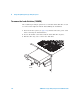
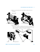
b If you have a 16902B or 16903A, slide the tray out being careful not
to catch the loose cables on anything.
6 For the PCI card location you will be using, remove the screw securing
the filler panel, swing the tall- slot plate out of the way if necessary,
and remove the filler panel.
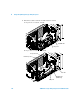
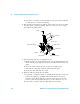
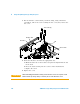
7 Insert the PCI card into the appropriate slot:
a Ensure that the tab at the bottom of the card is aligned with the slot
in the bottom of the CPU tray between the CPU board and the rear
panel.
b Press the card securely into the socket on the CPU board.
c For cards in a tall slot, swing the plate back into place.
d Secure the PCI card with the screw.
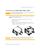
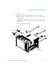
8 Slide the CPU tray back into the frame.
a If you have a 16900A, 16902A, or 16902B ensure that the connectors
between the CPU tray assembly and module interface board are
properly seated. First align the posts and holes then use the tray
levers to push the tray fully into place (see the figure in step 5a).
b If you have a 16903A, slide the CPU tray into the frame.
Plate over tall slots
Bottom of CPU tray
PCI card
Tab on card
Card socket
CPU board
Tall slot
Rear panel
Screw