Agilent 16900 Series Logic Analysis Systems Installation Guide A
Notices © Agilent Technologies, Inc. 2004-2009 Warranty No part of this manual may be reproduced in any form or by any means (including electronic storage and retrieval or translation into a foreign language) without prior agreement and written consent from Agilent Technologies, Inc. as governed by United States and international copyright laws. The material contained in this document is provided “as is,” and is subject to being changed, without notice, in future editions.
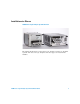
Installation at a Glance 16900 Series Logic Analysis System Overview The Agilent Technologies 16900 Series logic analysis systems are modular systems with slots for logic analyzer and other types of measurement modules.
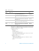
Table 1 Model comparisons Agilent model number Number of slots Multiframe Pro Display and resolution PCI expansion slots 16900A 6 Yes Uses external display, supports up to four external displays at up to 1600 x 1200 (with PCI video card) 2 full profile 1 low profile 16901A 2 Yes Built-in color touch screen display, 15 inch at 1024 x 768, supports external monitor (without additional PCI video card) 1 full profile 16902A 6 Yes Built-in color touch screen display, 12.
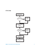
In This Guide Set up hardware and peripherals (Chapter 1) Are measurement modules installed ? No Install measurement modules (Chapter 2 & 3) Yes Go to Setting Up Multiframe Configurations (Chapter 5) Yes First-time set up considerations and Windows Welcome questions. (Chapter 4) Do you want to connect multiple frames together? No You are ready to make measurements. Go to Chapters 6 & 7 for post set up reference and problem solving.
16900 Series Logic Analysis Systems Installation Guide
Contents Installation at a Glance In This Guide 1 3 5 Setting Up Hardware To connect the mouse, keyboard, and monitor To connect to a LAN 17 To connect a printer 18 14 To make time-correlated measurements with an Agilent oscilloscope 2 19 Installing Logic Analyzer Cards and Probes Software Requirements To connect probes 23 24 To replace thumb screws on measurement modules 24 To install, remove, or replace measurement modules 26 16962A Logic Analyzer (1-card module) 30 16962A Logic Analyze
3 16950A, 16756/55/54/53A Logic Analyzer (1-card module) 48 16950A, 16756/55/54/53A Logic Analyzer (2-card module) 49 16950A, 16756/55/54/53A Logic Analyzer (3-card module) 50 16950A, 16756/55/54/53A Logic Analyzer (4-card module) 51 16950A, 16756/55/54/53A Logic Analyzer (5-card module) 52 16911A/10A Logic Analyzer (1-card module) 53 16911A/10A Logic Analyzer (2-card module) 54 16911A/10A Logic Analyzer (3-card module) 55 16911A/10A Logic Analyzer (4-card module) 56 16911A/10A Logic Anal
4 16720A Pattern Generator (3-card module) 73 16720A Pattern Generator (4-card module) 74 16720A Pattern Generator (5-card module) 75 First-Time Set Up First-Time Set Up Considerations 78 Determine Whether the Instrument will be Connected to the Network Get Network Setup Information 78 Answering Windows Welcome Questions 80 If expected Windows Welcome questions do not appear 81 Additional First Time Setup Steps 82 Establishing an Administrator Account (recommended for standalone and networked instr
6 Using and Updating the Logic Analysis System To locate information on using the logic analyzer Online Help 100 100 To locate specifications and characteristics 101 Electrical and Operating Environment Characteristics More Specifications and Characteristics 102 To perform backups 101 103 To install software 103 Agilent Logic Analysis System Software Optional Products 103 To change network settings 103 104 To change Windows Firewall settings 105 To give other applications/ports access through the f
16900A, 16902A, and 16902B logic analysis systems All 16900 Series logic analysis systems 126 If the Power LEDs do not come on 126 If you get a registry error and the system won’t boot If you can’t write/read CDs 126 126 If there are multiframe connection problems If there are network connection problems Using the System Recovery Software Contacting Agilent Service/Support A 125 127 129 130 130 Safety Notices Warnings 131 To clean the instrument Safety Symbols 132 132 Index 16900 Series Logic An
16900 Series Logic Analysis Systems Installation Guide
Agilent 16900 Series Logic Analysis Systems Installation Guide 1 Setting Up Hardware To connect the mouse, keyboard, and monitor 14 To connect to a LAN 17 To connect a printer 18 To make time-correlated measurements with an Agilent oscilloscope 19 A 13
1 Setting Up Hardware To connect the mouse, keyboard, and monitor The 16900A logic analysis system must have the system mouse and keyboard connected for the system to boot up properly. Once enabled on the LAN, the system can be operated remotely without a keyboard or mouse. Use of a monitor is optional for the 16901A, 16902A, 16902B, and 16903A. (The following rear panel figures are representative; yours may look different.) 1 Connect the provided PS/2 mouse and keyboard provided to the back of frame.
Setting Up Hardware 1 The touch off button switches the Windows desktop from one display device to another. A message will appear in one of the monitors telling you how to use this feature. 3 Connect the power cord supplied with your frame. NOTE The 16900A, 16902A, and 16902B have a special notched power cord in order to provide 1300W to the frame.
1 Setting Up Hardware 4 Allow a minimum of 15 cm (6 in.) spacing between instruments for proper cooling. 15 cm (6 in.) 16 15 cm (6 in.
Setting Up Hardware 1 To connect to a LAN Local area networks (LAN) are enabled outside of the logic analyzer application using the Windows network configuration wizard. 1 Connect the LAN cable(s) to the back of your logic analysis system. • Agilent recommends using a 1 Gbit LAN card when networking multiple frames. The 16902B and 16901A frames have an integrated 1 Gbit LAN interface.
1 Setting Up Hardware To connect a printer Local and network printers are added outside of the logic analyzer application using the Windows add printer wizard. 1 Connect the printer cable to the back of your logic analysis system. If using a network printer ensure the LAN cable is connected. 2 Click Start>Settings>Printers>Add Printer. 3 Follow the Windows add printer wizard instructions.
Setting Up Hardware 1 To make time-correlated measurements with an Agilent oscilloscope You can make time- correlated measurements between an Agilent 16900 Series logic analyzer and Agilent 5000, 6000, 548xx, 8000, or 80000 Series oscilloscopes. Measurements between the logic analyzer and Agilent oscilloscope are automatically de- skewed. The instruments communicate with one another through a LAN connection and Trigger In/Trigger Out.
1 20 Setting Up Hardware 16900 Series Logic Analysis Systems Installation Guide
Agilent 16900 Series Logic Analysis Systems Installation Guide 2 Installing Logic Analyzer Cards and Probes Software Requirements 23 To connect probes 24 To replace thumb screws on measurement modules 24 To install, remove, or replace measurement modules 26 16962A Logic Analyzer (1-card module) 30 16962A Logic Analyzer (2-card, 3-card, and 4-card modules) 16960A Logic Analyzer (1-card module) 37 16960A Logic Analyzer (2-card, 3-card, and 4-card modules) 16951/50B Logic Analyzer (1-card module) 43 16951/50B
2 Installing Logic Analyzer Cards and Probes 16760A Logic Analyzer (5-card module) 62 16752/51/50B/A, 16742/41/40A Logic Analyzer (1-card module) 16752/51/50B/A, 16742/41/40A Logic Analyzer (2-card module) 16752/51/50B/A, 16742/41/40A Logic Analyzer (3-card module) 16752/51/50B/A, 16742/41/40A Logic Analyzer (4-card module) 16752/51/50B/A, 16742/41/40A Logic Analyzer (5-card module) 22 63 64 65 66 67 16900 Series Logic Analysis Systems Installation Guide
Installing Logic Analyzer Cards and Probes 2 Software Requirements The following table gives you the Agilent Logic Analyzer software version required for logic analyzer measurement modules in the 16900A, 16902A, 16902B, or 16903A frames. For information on updating your logic analysis system software go to “To install software” on page 103. Table 2 Software Version Required, Frames Model Number Software Version 16903A 02.00 or higher 16902B 03.70 or higher 16902A 02.00 or higher 16901A 03.
2 Installing Logic Analyzer Cards and Probes To connect probes Probing is the key to effective and efficient use of logic analyzers. Agilent Technologies offers a wide variety of probing accessories that support general- purpose and application- specific measurement needs. We provide reliable, electrically and mechanically unobtrusive probes that make it easy to connect your Agilent logic analyzer to your system under test.
2 Installing Logic Analyzer Cards and Probes 3 Screw the module screw into the sleeve. Hex nut Thumb screw Retaining ring Module sleeve Module screw The 16900A/16902A logic analysis system comes with a set of 6 replacement thumb screws (16900- 68713), and the 16903A logic analysis system comes with a set of 2 replacement thumb screws (16903- 68713).
2 Installing Logic Analyzer Cards and Probes To install, remove, or replace measurement modules If you ordered your measurement modules with the frame, they will already be installed and you can skip this procedure. If you are using a measurement module from a 16700 Series logic analysis system you will need to replace the thumb screws. Begin with the instructions on page 24.
Installing Logic Analyzer Cards and Probes 2 2 Remove filler panels as shown in the following figure. a Loosen the thumb screws on the filler panels. b Rotate the ejector levers from the locked position to the open position. c Remove filler panels. Thumb screw Locked position Open position 3 If you are using a measurement module from a 16700 Series logic analysis system go to “To replace thumb screws on measurement modules” on page 24. If not, skip this step.
2 Installing Logic Analyzer Cards and Probes Insertion Order Removal Order 6 1 5 2 4 3 3 4 2 5 1 6 5 Seat the modules then rotate the ejector tabs to the locked position. Repeat for all modules or filler panels. Locking Order Ejecting Order 6 5 4 3 2 1 1 2 3 4 5 6 6 Tighten the thumb screws until finger tight in the same order used in step 5 above. 7 For correct air circulation, install filler panels in all unused card slots. Correct air circulation keeps the instrument from overheating.
Installing Logic Analyzer Cards and Probes 2 8 Refer to “First- Time Set Up” on page 77 to answer the Windows Welcome questions when you power up the logic analysis system for the first time.
2 Installing Logic Analyzer Cards and Probes 16962A Logic Analyzer (1-card module) A single- card module can be installed in any available slot. For a single card, the two 16960- 61602 flex cables (kit 16960- 60002 in the accessory pouch) are not used. NOTE Turn off the mainframe power before removing, replacing, or installing modules. For instructions on installing modules into the logic analysis system frame, refer to page 26.
2 Installing Logic Analyzer Cards and Probes 16962A Logic Analyzer (2-card, 3-card, and 4-card modules) Between cards, use a pair of 16960- 61602 flex cables (in the accessory pouch) to connect the modules. NOTE The 16962A logic analyzer module must only be combined with other 16962A modules. A 16962A combined set will default to the lowest memory depth in the set. NOTE Turn off the mainframe power before removing, replacing, or installing modules.
2 Installing Logic Analyzer Cards and Probes 1 Insert the lowest card about 1/3 of the way into the desired logic analyzer frame slot. 2 Before inserting the next card into the desired slot, attach the flex cables to the under side of the card: a Flip up the connector actuator with your thumb or index finder. Do not use any type of tool to open the actuator.
Installing Logic Analyzer Cards and Probes 2 b Place the flex cable into the connector, exposed conductive traces towards the card, so that the flex cable ears are secured by the connector guides. c Close the connector actuator. d Repeat for the opposite under- side flex cable and connector.
2 Installing Logic Analyzer Cards and Probes 3 Now, slide the next card about 1/3 of the way into its slot, so that it is aligned with the lower card. 4 Attach the flex cables to the top side of the lower card: a Flip up the connector actuator with your thumb or index finder. Do not use any type of tool to open the actuator. b Place the flex cable into the connector, exposed conductive traces towards the card, so that the flex cable ears are secured by the connector guides.
Installing Logic Analyzer Cards and Probes 2 6 To verify the flex cables are installed correctly, use an ohm meter to check continuity between the pair of test points associated with each connector used. If there is continuity (0 ohms), the flex cable is seated correctly in the connector. If there is no continuity (infinite ohms), the flex cable is not seated correctly. Repeat the flex cable attachment steps, and check the continuity again.
2 Installing Logic Analyzer Cards and Probes While maintaining alignment with the cards as a set, insert them the rest of the way into the slots, seat them, lock the ejector tabs, and tighten the thumb screws.
Installing Logic Analyzer Cards and Probes 2 16960A Logic Analyzer (1-card module) A single- card module can be installed in any available slot. For a single card, the two 16960- 61601 flex cables (kit 16960- 60001 in the accessory pouch) are not used. NOTE Turn off the mainframe power before removing, replacing, or installing modules. For instructions on installing modules into the logic analysis system frame, refer to page 26.
2 Installing Logic Analyzer Cards and Probes 16960A Logic Analyzer (2-card, 3-card, and 4-card modules) Between cards, use a pair of 16960- 61601 flex cables (in the accessory pouch) to connect the modules. NOTE The 16960A logic analyzer module must only be combined with other 16960A modules. A 16960A combined set will default to the lowest memory depth in the set. NOTE Turn off the mainframe power before removing, replacing, or installing modules.
Installing Logic Analyzer Cards and Probes 2 1 Insert the lowest card about 1/3 of the way into the desired logic analyzer frame slot. 2 Before inserting the next card into the desired slot, attach the flex cables to the under side of the card: a Flip up the connector actuator with your thumb or index finder. Do not use any type of tool to open the actuator.
2 Installing Logic Analyzer Cards and Probes b Place the flex cable into the connector, exposed conductive traces towards the card, so that the flex cable ears are secured by the connector guides. c Close the connector actuator. d Repeat for the opposite under- side flex cable and connector.
Installing Logic Analyzer Cards and Probes 2 3 Now, slide the next card about 1/3 of the way into its slot, so that it is aligned with the lower card. 4 Attach the flex cables to the top side of the lower card: a Flip up the connector actuator with your thumb or index finder. Do not use any type of tool to open the actuator. b Place the flex cable into the connector, exposed conductive traces towards the card, so that the flex cable ears are secured by the connector guides.
2 Installing Logic Analyzer Cards and Probes 6 To verify the flex cables are installed correctly, use an ohm meter to check continuity between the pair of test points associated with each connector used. If there is continuity (0 ohms), the flex cable is seated correctly in the connector. If there is no continuity (infinite ohms), the flex cable is not seated correctly. Repeat the flex cable attachment steps, and check the continuity again.
Installing Logic Analyzer Cards and Probes 2 16951/50B Logic Analyzer (1-card module) Each card shipped stand- alone has the 2 x 15 cable connected in the single- card module configuration. The 2 x 50 cables in the accessory pouch are not used. A single- card module can be installed in any available slot. NOTE Turn off the mainframe power before removing, replacing, or installing modules. For instructions on installing modules into the logic analysis system frame, refer to page 26.
2 Installing Logic Analyzer Cards and Probes 16951/50B Logic Analyzer (2-card module) Use two 2 x 15 cables and two 2 x 50 cables (in the accessory pouch) to connect the modules. NOTE Turn off the mainframe power before removing, replacing, or installing modules. For instructions on installing modules into the logic analysis system frame, refer to page 26. NOTE The 16950B logic analyzer module must only be combined with another 16950B module.
Installing Logic Analyzer Cards and Probes 2 16951/50B Logic Analyzer (3-card module) Use three 2 x 15 cables and four 2 x 50 cables (in the accessory pouch) to connect the modules. NOTE Turn off the mainframe power before removing, replacing, or installing modules. For instructions on installing modules into the logic analysis system frame, refer to page 26. NOTE The 16950B logic analyzer module must only be combined with other 16950B modules.
2 Installing Logic Analyzer Cards and Probes 16951/50B Logic Analyzer (4-card module) Use four 2 x 15 cables and six 2 x 50 cables (in the accessory pouch) to connect the modules. NOTE Turn off the mainframe power before removing, replacing, or installing modules. For instructions on installing modules into the logic analysis system frame, refer to page 26. NOTE The 16950B logic analyzer module must only be combined with other 16950B modules.
Installing Logic Analyzer Cards and Probes 2 16951/50B Logic Analyzer (5-card module) Use five 2 x 15 cables and eight 2 x 50 cables (in the accessory pouch) to connect the modules. NOTE Turn off the mainframe power before removing, replacing, or installing modules. For instructions on installing modules into the logic analysis system frame, refer to page 26. NOTE The 16950B logic analyzer module must only be combined with other 16950B modules.
2 Installing Logic Analyzer Cards and Probes 16950A, 16756/55/54/53A Logic Analyzer (1-card module) Each card shipped stand- alone has the 2 x 15 cable connected in the single- card module configuration. The 2 x 50 cables in the accessory pouch are not used. A single- card module can be installed in any available slot. NOTE Turn off the mainframe power before removing, replacing, or installing modules. For instructions on installing modules into the logic analysis system frame, refer to page 26.
2 Installing Logic Analyzer Cards and Probes 16950A, 16756/55/54/53A Logic Analyzer (2-card module) Use two 2 x 15 cables and two 2 x 50 cables (in the accessory pouch) to connect the modules. NOTE Turn off the mainframe power before removing, replacing, or installing modules. For instructions on installing modules into the logic analysis system frame, refer to page 26. NOTE You can combine any combination of 16753A, 16754A, 16755A, 16756A, and 16950A logic analyzer modules in a 2-card set.
2 Installing Logic Analyzer Cards and Probes 16950A, 16756/55/54/53A Logic Analyzer (3-card module) Use three 2 x 15 cables and four 2 x 50 cables (in the accessory pouch) to connect the modules. NOTE Turn off the mainframe power before removing, replacing, or installing modules. For instructions on installing modules into the logic analysis system frame, refer to page 26. NOTE You can combine any combination of 16753A, 16754A, 16755A, 16756A, and 16950A logic analyzer modules in a 3-card set.
2 Installing Logic Analyzer Cards and Probes 16950A, 16756/55/54/53A Logic Analyzer (4-card module) Use four 2 x 15 cables and six 2 x 50 cables (in the accessory pouch) to connect the modules. NOTE Turn off the mainframe power before removing, replacing, or installing modules. For instructions on installing modules into the logic analysis system frame, refer to page 26. NOTE You can combine any combination of 16753A, 16754A, 16755A, 16756A, and 16950A logic analyzer modules in a 4-card set.
2 Installing Logic Analyzer Cards and Probes 16950A, 16756/55/54/53A Logic Analyzer (5-card module) Use five 2 x 15 cables and eight 2 x 50 cables (in the accessory pouch) to connect the modules. NOTE Turn off the mainframe power before removing, replacing, or installing modules. For instructions on installing modules into the logic analysis system frame, refer to page 26. NOTE You can combine any combination of 16753A, 16754A, 16755A, 16756A, and 16950A logic analyzer modules in a 5-card set.
Installing Logic Analyzer Cards and Probes 2 16911A/10A Logic Analyzer (1-card module) Each card shipped stand- alone has the 2 x 15 cable connected in the single- card module configuration. The 2 x 50 cables in the accessory pouch are not used. A single- card module can be installed in any available slot. NOTE Turn off the mainframe power before removing, replacing, or installing modules. For instructions on installing modules into the logic analysis system frame, refer to page 26.
2 Installing Logic Analyzer Cards and Probes 16911A/10A Logic Analyzer (2-card module) Use two 2 x 15 cables and two 2 x 50 cables (in the accessory pouch) to connect the modules. 54 NOTE Turn off the mainframe power before removing, replacing, or installing modules. For instructions on installing modules into the logic analysis system frame, refer to page 26. NOTE You can combine the same model numbers only (16910A in a 2-card set or 16911A in a 2-card set).
2 Installing Logic Analyzer Cards and Probes 16911A/10A Logic Analyzer (3-card module) Use three 2 x 15 cables and four 2 x 50 cables (in the accessory pouch) to connect the modules. NOTE Turn off the mainframe power before removing, replacing, or installing modules. For instructions on installing modules into the logic analysis system frame, refer to page 26. NOTE You can combine the same model numbers only (16910A in a 3-card set or 16911A in a 3-card set).
2 Installing Logic Analyzer Cards and Probes 16911A/10A Logic Analyzer (4-card module) Use four 2 x 15 cables and six 2 x 50 cables (in the accessory pouch) to connect the modules. 56 NOTE Turn off the mainframe power before removing, replacing, or installing modules. For instructions on installing modules into the logic analysis system frame, refer to page 26. NOTE You can combine the same model numbers only (16910A in a 4-card set or 16911A in a 4-card set).
2 Installing Logic Analyzer Cards and Probes 16911A/10A Logic Analyzer (5-card module) Use five 2 x 15 cables and eight 2 x 50 cables (in the accessory pouch) to connect the modules. NOTE Turn off the mainframe power before removing, replacing, or installing modules. For instructions on installing modules into the logic analysis system frame, refer to page 26. NOTE You can combine the same model numbers only (16910A in a 5-card set or 16911A in a 5-card set).
2 Installing Logic Analyzer Cards and Probes 16760A Logic Analyzer (1-card module) A single 16760A logic analyzer module will have the 2 x 10 cable connected in the single- card configuration. NOTE Turn off the mainframe power before removing, replacing, or installing modules following the procedures on page 26. The order of pods on the card’s rear panel is: Pod 2 Pod 1 In a multi- card set, pods are indexed starting with the master card, then with the expander cards from the bottom up.
2 Installing Logic Analyzer Cards and Probes 16760A Logic Analyzer (2-card module) Use two 2 x 10 cables and two 2 x 40 cables (in the accessory pouch) to connect the modules. NOTE Turn off the mainframe power before removing, replacing, or installing modules following the procedures on page 26.
2 Installing Logic Analyzer Cards and Probes 16760A Logic Analyzer (3-card module) Use three 2 x 10 cables and four 2 x 40 cables (in the accessory pouch) to connect the modules. NOTE 60 Turn off the mainframe power before removing, replacing, or installing modules following the procedures on page 26.
2 Installing Logic Analyzer Cards and Probes 16760A Logic Analyzer (4-card module) Use four 2 x 10 cables and six 2 x 40 cables (in the accessory pouch) to connect the modules. NOTE Turn off the mainframe power before removing, replacing, or installing modules following the procedures on page 26.
2 Installing Logic Analyzer Cards and Probes 16760A Logic Analyzer (5-card module) Use five 2 x 10 cables and eight 2 x 40 cables (in the accessory pouch) to connect the modules. NOTE 62 Turn off the mainframe power before removing, replacing, or installing modules following the procedures on page 26.
Installing Logic Analyzer Cards and Probes 2 16752/51/50B/A, 16742/41/40A Logic Analyzer (1-card module) Each card shipped stand- alone has the 2 x 10 cable connected in the single- card module configuration. A single- card module can be installed in any available slot. NOTE Turn off the mainframe power before removing, replacing, or installing modules. For instructions on installing modules into the logic analysis system frame, refer to page 26.
2 Installing Logic Analyzer Cards and Probes 16752/51/50B/A, 16742/41/40A Logic Analyzer (2-card module) Use two 2 x 10 cables and two 2 x 40 cables (in the accessory pouch) to connect the modules. 64 NOTE Turn off the mainframe power before removing, replacing, or installing modules. For instructions on installing modules into the logic analysis system frame, refer to page 26. NOTE Measurement modules with different model numbers cannot be connected together in multi-card modules.
Installing Logic Analyzer Cards and Probes 2 16752/51/50B/A, 16742/41/40A Logic Analyzer (3-card module) Use three 2 x 10 cables and four 2 x 40 cables (in the accessory pouch) to connect the modules. NOTE Turn off the mainframe power before removing, replacing, or installing modules. For instructions on installing modules into the logic analysis system frame, refer to page 26. NOTE Measurement modules with different model numbers cannot be connected together in multi-card modules.
2 Installing Logic Analyzer Cards and Probes 16752/51/50B/A, 16742/41/40A Logic Analyzer (4-card module) Use four 2 x 10 cables and six 2 x 40 cables (in the accessory pouch) to connect the modules. 66 NOTE Turn off the mainframe power before removing, replacing, or installing modules. For instructions on installing modules into the logic analysis system frame, refer to page 26. NOTE Measurement modules with different model numbers cannot be connected together in multi-card modules.
Installing Logic Analyzer Cards and Probes 2 16752/51/50B/A, 16742/41/40A Logic Analyzer (5-card module) Use five 2 x 10 cables and eight 2 x 40 cables (in the accessory pouch) to connect the modules NOTE Turn off the mainframe power before removing, replacing, or installing modules. For instructions on installing modules into the logic analysis system frame, refer to page 26. NOTE Measurement modules with different model numbers cannot be connected together in multi-card modules.
2 68 Installing Logic Analyzer Cards and Probes 16900 Series Logic Analysis Systems Installation Guide
Agilent 16900 Series Logic Analysis Systems Installation Guide 3 Installing Pattern Generator Cards Software Requirements 70 16720A Pattern Generator (1-card module) 16720A Pattern Generator (2-card module) 16720A Pattern Generator (3-card module) 16720A Pattern Generator (4-card module) 16720A Pattern Generator (5-card module) 71 72 73 74 75 A 69
3 Installing Pattern Generator Cards Software Requirements The following table gives you the Agilent Logic Analyzer software version required for pattern generator measurement modules in the 16900A, 16902A, 16902B, or 16903A frames. For the software version required by frames, see Table 2 on page 23. For information on updating your logic analysis system software go to “To install software” on page 103.
Installing Pattern Generator Cards 3 16720A Pattern Generator (1-card module) Each card shipped stand- alone has the 2 x 10 cable connected in the single- card module configuration. A single- card module can be installed in any available slot. NOTE Turn off the mainframe power before removing, replacing, or installing modules. For instructions on installing modules into the logic analysis system frame, refer to page 26.
3 Installing Pattern Generator Cards 16720A Pattern Generator (2-card module) Use two 2 x 10 cables to connect the modules. NOTE Turn off the mainframe power before removing, replacing, or installing modules. For instructions on installing modules into the logic analysis system frame, refer to page 26.
Installing Pattern Generator Cards 3 16720A Pattern Generator (3-card module) Use three 2 x 10 cables to connect the modules. NOTE Turn off the mainframe power before removing, replacing, or installing modules. For instructions on installing modules into the logic analysis system frame, refer to page 26.
3 Installing Pattern Generator Cards 16720A Pattern Generator (4-card module) NOTE Turn off the mainframe power before removing, replacing, or installing modules. For instructions on installing modules into the logic analysis system frame, refer to page 26. 1 Carefully slide the 4 cards half way into the mainframe slots. 2 Use four 2 x 10 cables to connect the modules. Cable the bottom Expander Card to the Master Card first. Then cable the upper two Expander Cards to the Master Card.
Installing Pattern Generator Cards 3 16720A Pattern Generator (5-card module) NOTE Turn off the mainframe power before removing, replacing, or installing modules. For instructions on installing modules into the logic analysis system frame, refer to page 26. 1 Carefully slide the 4 cards half way into the mainframe slots. 2 Use five 2 x 10 cables to connect the modules. Cable the bottom two Expander Cards to the Master Card first. Then cable the upper two Expanders to the Master Card.
3 76 Installing Pattern Generator Cards 16900 Series Logic Analysis Systems Installation Guide
Agilent 16900 Series Logic Analysis Systems Installation Guide 4 First-Time Set Up First-Time Set Up Considerations 78 Answering Windows Welcome Questions 80 Additional First Time Setup Steps 82 A 77
4 First-Time Set Up First-Time Set Up Considerations The first time you turn on the logic analysis system, the Windows Welcome session starts. Your logic analyzer configuration and the answers to the Windows Welcome questions are affected by how you choose to use the logic analyzer. NOTE Use the Enter and arrow keys on the attached keyboard. The logic analyzer front-panel keys do not work until Windows is running.
4 First-Time Set Up Information you may require to complete your network configuration may include, but is not limited to, • The Workgroup or Domain name. • Methodology for assigning IP addresses at your site (for example, DHCP). • Domain Name Service (DNS). This can also be obtained automatically. • Other network information that may be readily available from your network administrator.
4 First-Time Set Up Answering Windows Welcome Questions Once you have determined how you want to use your logic analyzer and your network configuration, power up your logic analyzer and answer the Windows Welcome questions. Table 5 Answering Windows Welcome Questions Standalone (No LAN) Workgroup Domain Help protect your PC N/A Choose “Help protect my PC by turning on Automatic Updates now”. Choose “Help protect my PC by turning on Automatic Updates now”.
First-Time Set Up Table 5 4 Answering Windows Welcome Questions (continued) Standalone (No LAN) Workgroup Domain (If LAN connected) Will this computer connect to the Internet directly, or through a network? N/A Choose "Yes, through a network" (Agilent does not support connecting to the internet through a modem directly connected to the logic analyzer.) N/A (If LAN is not connected) Windows unable to determine LAN connectivity. N/A You are told to set up LAN later.
4 First-Time Set Up Additional First Time Setup Steps Establishing an Administrator Account (recommended for standalone and networked instruments) Agilent recommends that you set up an Administrator account for your logic analysis system. You have to be logged in to the Administrator account to do the following: • Install most software (applies whether the instrument is networked or standalone). • Change the workgroup. • Perform "Windows Updates". • Change firewall settings.
Agilent 16900 Series Logic Analysis Systems Installation Guide 5 Setting Up Multiframe Configurations Setting Up Simple Multiframe Configurations 84 Setting Up a Performance Multiframe Configuration 92 Other Multiframe Configuration Notes 97 If you need to make time- correlated measurements with more logic analysis channels than can be installed into a single logic analysis system frame, you can connect multiple 16900A, 16901A, 16902A, and 16902B frames together in a multiframe logic analysis system.
5 Setting Up Multiframe Configurations Setting Up Simple Multiframe Configurations Simple multiframe configurations are useful when you are using one or more logic analysis systems in a variety of configurations where sometimes you are using them as distinct analyzers and sometimes you need to use them as a multiframe system to correlate a variety of buses.
5 Setting Up Multiframe Configurations Simple 100 Base-T Multiframe Configuration Interface to Corporate LAN 100 Base-T Switch 16901A/902A/902B (or 16900A with monitor) Multiframe Cable 16900A/901A/902A/902B Multiframe Cable 16900A/901A/902A/902B In the simple 100 Base- T multiframe configuration, all of the frames are connected to the network using their 100 Base- T LAN port.
5 Setting Up Multiframe Configurations Simple 1000 Base-T Multiframe Configuration Interface to Corporate LAN 1000 Base-T Switch 16901A/902A/902B (or 16900A with monitor) Multiframe Cable 16900A/901A/902A/902B Multiframe Cable 16900A/901A/902A/902B In the simple 1000 Base- T multiframe configuration, all of the frames are connected to the network using their 1000 Base- T LAN port.
5 Setting Up Multiframe Configurations Rules for Simple Multiframe Configurations In addition to the earlier guidelines on page 83: • Choose one of the frames to run the Agilent Logic Analyzer application on. If you only run the application on one frame, all your configurations will be there (and will be easier to find). Also, there are I/O and node- locked license file advantages when the application is run on one frame (see “Other Multiframe Configuration Notes” on page 97).
5 Setting Up Multiframe Configurations 4 Power up all frames. As the operating system loads, it will: • Configure the connection to the corporate LAN. • Start various services. • Start the logic analyzer service. 5 Log in to the frame you chose to run the Agilent Logic Analyzer application on, and wait for the application to start. NOTE Depending on your multiframe connection topology, it may take several seconds for the Agilent Logic Analyzer application to start.
5 Setting Up Multiframe Configurations 6 If you are not able to see the multiframe system in the Overview window, do the following: a Exit the Agilent Logic Analyzer application. b Power down all frames. c Disconnect and reconnect the multiframe cables to all frames. Make sure the output of one frame is connected to the input of the next. d Power up the frames.
5 Setting Up Multiframe Configurations • Run the Agilent Logic Analyzer application on your remote PC and connect to the multiframe system by going online and connecting to the frame. With this option: • Your performance may vary because analyzer data from all logic analysis frames must be sent over LAN to your locally running application.
5 Setting Up Multiframe Configurations Creating a Simple 2-Frame w/Crossover Cable Configuration 1 Set up the two frames in the simple 100 Base- T multiframe configuration by following the instructions in “Creating Simple Multiframe Configurations” on page 87. 2 If the Agilent Logic Analyzer application is running on one of the frames, exit the application. 3 Connect a special cross- over LAN cable between the two frames’ 1000 Base- T LAN ports.
5 Setting Up Multiframe Configurations Setting Up a Performance Multiframe Configuration Interface to Corporate LAN 1000 Base-T Switch 16900A/901A/902A/902B Performance PC Multiframe Cable 16900A/901A/902A/902B Multiframe Cable 16900A/901A/902A/902B 92 16900 Series Logic Analysis Systems Installation Guide
5 Setting Up Multiframe Configurations In the performance multiframe configuration, you run the Agilent Logic Analyzer application on a high- performance PC or server. This is useful if you trying to maximize multiframe logic analysis system performance.
5 Setting Up Multiframe Configurations • Because the Agilent Logic Analyzer application runs on the performance PC connected remotely to a frame, the frame’s front panel knobs and buttons are not functional. 5 Power down all of the frames and the performance PC. 6 Connect multiframe cables between the frames as shown. (Output open) (Input open) Output Output Input Input One frame’s output is connected to the next frame’s input.
5 Setting Up Multiframe Configurations If the application starts without errors, and the multiframe system appears in the Overview window, you are almost ready to use the multiframe system. Exit the application, and continue on step 10. 9 If you are not able to see the multiframe system in the Overview window on the frame, do the following: a Exit the Agilent Logic Analyzer application. b Power down all frames. c Disconnect and reconnect the multiframe cables between all frames. d Power up all frames.
5 Setting Up Multiframe Configurations 10 Power up the performance PC, log in, start the Agilent Logic Analyzer application, and connect to one of the frames remotely: a When the application is starting and the Offline Startup Options dialog appears, click “Go Online...”. b In the Select System to Use dialog, click “Add System”. c In the Frame Host Name or IP Address dialog, enter the name of the frame, and click “OK”. d Select the system that was just added and click “Details...”.
5 Setting Up Multiframe Configurations Other Multiframe Configuration Notes Some other things to be aware of when using multiframe configurations: • The multiframe cable is used for time correlation, cross- triggering, and multiframe setup; all other inter- frame communication takes place over LAN. • Network interfaces need to see a direct path to the DHCP server. Otherwise, power- up times will be slow. Use static IP addresses if a direct path to the DHCP server is not available.
5 98 Setting Up Multiframe Configurations 16900 Series Logic Analysis Systems Installation Guide
Agilent 16900 Series Logic Analysis Systems Installation Guide 6 Using and Updating the Logic Analysis System To locate information on using the logic analyzer 100 To locate specifications and characteristics 101 To perform backups 103 To install software 103 To change network settings 104 To change Windows Firewall settings 105 To power off the system 110 To remove the hard disk drive (16902B) 112 To install interface cards (16900A, 16902A, 16902B, or 16903A) 113 To install interface cards (16901A) 118 To
6 Using and Updating the Logic Analysis System To locate information on using the logic analyzer Online Help Go to online help for information on using your logic analyzer. Getting Started Use the tutorial in on- line help to get an overview of logic analyzer basics. The measurement examples show you the typical order of steps to set up and run a measurement.
6 Using and Updating the Logic Analysis System To locate specifications and characteristics Electrical and Operating Environment Characteristics The following operating characteristics are not specifications, but are typical operating characteristics for the Agilent 16900 Series logic analysis systems.
6 Using and Updating the Logic Analysis System More Specifications and Characteristics More specifications and characteristics for your instrument and measurement modules are in the online help. To find them go to: 1 Click Help>Help Topics. 2 Click Reference>Specifications and Characteristics.
Using and Updating the Logic Analysis System 6 To perform backups Back up your information regularly to keep your archived data and files up- to- date. Use the Backup utility in Windows XP and back up to CD- Rs or to another machine. To install software Agilent Logic Analysis System Software The Agilent 16900 Series logic analysis systems are shipped with software already installed, including any licensed optional products that you may have purchased.
6 Using and Updating the Logic Analysis System To change network settings To make network changes after the first- time power up: • To change from a workgroup to a domain or vice versa, click Start then right click on My Computer and select Properties. Select the Computer Name tab and click Change. • To change network connection properties, click Start>Control Panel>Network Connections. Select the connection you want to change and click Change settings of this connection.
Using and Updating the Logic Analysis System 6 To change Windows Firewall settings When 16900 Series logic analysis systems are shipped from the factory, the Windows Firewall is enabled and set up with the exceptions required by the logic analysis system. To give other applications/ports access through the firewall For example, you may need to change firewall settings in order to: • Use NetOp to remotely control the logic analysis system. • Use RealVNC to remotely control the logic analysis system.
6 Using and Updating the Logic Analysis System 3 In the Windows Firewall dialog, click the Exceptions tab. 4 In the Exceptions tab, if the program or service is listed, check its box to enable it; otherwise, click Add Program... to give unlisted applications permission to penetrate the firewall, or click Add Port... to give unlisted ports access through the firewall. Refer to the application’s documentation for information on port numbers or other firewall setup information.
Using and Updating the Logic Analysis System 6 To restore the logic analysis system firewall defaults 1 From the Windows Start menu, choose Start>Control Panel. 2 In the Control Panel window, open Windows Firewall.
6 Using and Updating the Logic Analysis System 3 In the Windows Firewall dialog, click the Advanced tab. 4 In the Advanced tab, click Restore Defaults to restore the default Windows Firewall settings. 5 In the confirmation dialog, Click Yes. 6 Click OK to close the Windows Firewall dialog. 7 From the Windows Start menu, choose Start>Run; then, enter or select the file “C:\Program Files\Agilent Technologies\Logic Analyzer\ agFirewSP2.wsf”, and click OK.
Using and Updating the Logic Analysis System 6 The logic analysis system firewall defaults also enable the following ICMP (Internet Control Message Protocol) settings: • Allow incoming echo request. • Allow outgoing destination unreachable. • Allow outgoing time exceeded. NOTE Note that there are separate Windows Firewall profiles: Domain for when the computer has domain membership, and Standard for when the computer has workgroup membership.
6 Using and Updating the Logic Analysis System To power off the system You can power off the logic analysis system using Windows Shutdown or a short press of the power button. NOTE When powering off the logic analysis system, wait until the fans stop turning (about 15 seconds) before turning the logic analysis system back on. This ensures that internal circuitry restarts in a known state.
6 Using and Updating the Logic Analysis System Using a Long Press of the Power Button CAUTION Only use a long press of the power button when the logic analysis system is unresponsive to Windows Shutdown or a short press of the power button. Pressing the power button for more than 4 seconds will power the system down abruptly: • Programs that are running will not be shut down. Any data that has not been written to the disk will be lost. • Turns off the power supply.
6 Using and Updating the Logic Analysis System To remove the hard disk drive (16902B) The 16902B logic analysis system has a removable hard disk drive. It can be removed and replaced without disassembling the instrument. 1 Power down the system (see page 110) and disconnect the power cable before removing the hard disk drive. 2 Loosen the thumb screw that holds the hard disk drive in place. 3 Pull the drive tray out to remove the disk drive.
6 Using and Updating the Logic Analysis System To install interface cards (16900A, 16902A, 16902B, or 16903A) Electrostatic discharge can damage electronic components. Use grounded wrist straps and mats when performing this procedure. CAUTION ! The following instructions show you how to properly remove/replace the CPU tray and install PCI cards. 1 Power down the system and disconnect the power cable before installing interface cards. 2 Remove the cover.
6 Using and Updating the Logic Analysis System 3 Disconnect cables from the module interface board.
Using and Updating the Logic Analysis System 6 4 Remove screws from the back of the CPU tray using a Torx T- 10 screwdriver. 16902B or 16903A 16900A or 16902A 7 screws 9 screws 5 Remove the CPU tray. a If you have a 16900A or 16902A, use the tray lever to disconnect the CPU board from the module interface board then slide the tray out being careful not to catch the loose cables on anything.
6 Using and Updating the Logic Analysis System b If you have a 16902B or 16903A, slide the tray out being careful not to catch the loose cables on anything. 6 For the PCI card location you will be using, remove the screw securing the filler panel, swing the tall- slot plate out of the way if necessary, and remove the filler panel.
Using and Updating the Logic Analysis System 6 9 Insert and tighten the screws shown in step 4. 10 Reconnect the CPU cables shown in step 3. 1 Gbit LAN Card If you ordered a 1 Gbit LAN card with your 16900A, 16902A, or 16903A frame (Option 014) it will already be installed. If you order the 1 Gbit LAN card separately (as model E5860A), you need to install the the card following the instructions beginning on page 113. To order a 1 Gbit LAN card go to: http://www.agilent.
6 Using and Updating the Logic Analysis System To install interface cards (16901A) Electrostatic discharge can damage electronic components. Use grounded wrist straps and mats when performing this procedure. CAUTION ! The following instructions show you how to properly remove the 16901A logic analysis system cover, install interface cards, and replace the cover. 1 Power down the system and disconnect the power cable before installing interface cards.
6 Using and Updating the Logic Analysis System 2 Remove the cover: a Using a Torx T20 screwdriver, remove the handle assembly. b Using a Torx T10 screwdriver, remove 6 screws that secure the cover to the chassis. Optional: Removing the shroud may make it easier to remove and replace the cover. In this case, remove 4 T10 screws; then, remove the shroud. c Slide the cover back to remove.
6 Using and Updating the Logic Analysis System 3 For the interface card location you will be using, using a Torx T10 screwdriver, remove the screw securing the slot cover; then, remove the slot cover. T-10 screws (2) Display cable PCI cable Tab Slots in deck 4 Insert the interface card into the appropriate slot: a Ensure that the tab on the board’s rear panel is aligned with the slot in the deck. b Press the board securely into the socket on the motherboard. c Replace the screw. 5 Replace the cover.
6 Using and Updating the Logic Analysis System To replace the CPU battery 1 Power down the system and disconnect the power cable before replacing the CPU battery. 2 Access the motherboard using the steps described in “To install interface cards (16900A, 16902A, 16902B, or 16903A)” on page 113 or “To install interface cards (16901A)” on page 118. 3 Using a 1/8 inch flat- blade screwdriver, gently pry the battery from the battery receptacle.
6 122 Using and Updating the Logic Analysis System 16900 Series Logic Analysis Systems Installation Guide
Agilent 16900 Series Logic Analysis Systems Installation Guide 7 Solving Problems Running Self-Tests 124 If the logic analysis system powers itself down 125 If the Power LEDs do not come on 126 If you get a registry error and the system won’t boot 126 If you can’t write/read CDs 126 If there are multiframe connection problems 127 If there are network connection problems 129 Using the System Recovery Software 130 Contacting Agilent Service/Support 130 A 123
7 Solving Problems Running Self-Tests 1 In the Agilent logic analyzer application, click Help>Self Test. 2 In the analysis system Self Test dialog, double click on the test you want to run.
7 Solving Problems If the logic analysis system powers itself down 16900A, 16902A, and 16902B logic analysis systems The power LEDs on the frame help to figure out why a frame has powered itself down. For safety purposes, when any of these LEDs are lit the frame will not power back up until the power cord has been disconnected and then reconnected. View LEDs through these holes Internal location The colors indicate: • Green — front power supply failure. • Yellow — side power supply failure.
7 Solving Problems All 16900 Series logic analysis systems If the system warns you it is powering down before it powers down, the dialog will describe the problem (such as a fan/overtemp problem). If the logic analysis system just powers down, it is likely a power supply problem.
7 Solving Problems with your antivirus software to check for and remove viruses. Viruses can sometimes prevent Windows from recognizing the drive. ✔ The CD drive must be parallel to the ground when writing to disk. CDs may not be readable in any CD- ROM drive if it was not. ✔ If a CD fails, clean it by wiping it off with a clean dry rag and then try again. If it continues to fail, insert another CD to eliminate the possibility that the original CD is defective.
7 Solving Problems 1 Choose Start>Control Panel. In the Control Panel window, open Network Connections. 2 Right- click on the LAN connection and select Properties. 3 Click on Configure and then select the Advanced tab. 4 Select Jumbo Frames and the Value.
7 Solving Problems If there are network connection problems See the “Network Troubleshooting Guide” topic in the Agilent Logic Analyzer application’s online help. Briefly: • The Windows Firewall must be set to allow access to the “Agilent Logic Analysis” service in order use remote and multiframe connections (see “To restore the logic analysis system firewall defaults” on page 107).
7 Solving Problems Using the System Recovery Software Restoring your system software might be necessary for the following reasons: • Hard drive failure. • Virus in the system or unstable system. • Intentional disk clean - for example if you are passing the system to another team or returning it to a rental company and you do not want any data left on it. You will need to have a keyboard and mouse connected. Follow the instructions provided with the recovery CD or DVD to restore your system software.
Agilent 16900 Series Logic Analysis Systems Installation Guide A Safety Notices This apparatus has been designed and tested in accordance with IEC Publication 1010, Safety Requirements for Measuring Apparatus, and has been supplied in a safe condition. This is a Safety Class I instrument (provided with terminal for protective earthing). Before applying power, verify that the correct safety precautions are taken (see the following warnings).
A Safety Notices • Service instructions are for trained service personnel. To avoid dangerous electric shock, do not perform any service unless qualified to do so. Do not attempt internal service or adjustment unless another person, capable of rendering first aid and resuscitation, is present. • Do not install substitute parts or perform any unauthorized modification to the instrument. • Capacitors inside the instrument may retain a charge even if the instrument is disconnected from its source of supply.
A Safety Notices Earth terminal symbol: Used to indicate a circuit common connected to grounded chassis.
A 134 Safety Notices 16900 Series Logic Analysis Systems Installation Guide
Index Numerics 16720A, installation, 71 16742/41/40A, installation, 63 16752/51/50A/B, installation, 63 16756/55/54/53A installation, 48 16760A, installation, 58 16900A, 4 16901A, 4 16902A, 4 16902B, 4 16903A, 4 16911/10A installation, 53 16950A installation, 48 16951/50B, installation, 43 16960A, installation, 37 16962A, installation, 30 A accessories included, 4 optional, 4 administrator, 78 administrator account, 82 Agilent web probes, 24 service/support, 125, 130 air circulation, 15, 28 altitude, 101 a
Index J O S jumbo frames setting, 127 online help, 100 optional accessories, 4 optional tools, 103 ordering thumb screws, 24, 26 oscilloscope time markers, 19 oscilloscope, time correlation, 19 overheating, 15 overview, 3 overview flowchart, 5 safety notices, 131 symbols, 131 screw replacement, 24, 26 self tests, 124 service contacting Agilent, 130 ground instrument, 113, 118 ground modules, 26, 111 web address, 125 shut down system, 110 software add-in, 103 installation, 78, 82, 103 updating, 103 ver
Index virus software, 17, 82 W warnings, 131 web address probes, 24 service/support, 125 windows power problems, 126 updates, 82 welcome, 78 welcome questions, 80 Windows Firewall settings changing, 105 workgroup, 78 changing, 82 16900 Series Logic Analysis Systems Installation Guide 137
Index 138 16900 Series Logic Analysis Systems Installation Guide