
User`s guide


Agilent 16440A User’s Guide, Edition 5 5
User's Guide
Operation
• Controlling the selector by using the B1500A
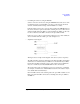
Selector connections can be set by using the SMU/PG Selector tab screen of the
Configuration window. And the PGU open can be set by using the Advanced
window of the Measurement Setup. See the B1500A User’s Guide.
If the Input/Output Path is set to Normally PGU (AUX) in the SMU/PG Selector
tab screen, the selector performs automatic switching in every test. The selector
channel normally makes the “PGU on” state and makes the “SMU on” state only
for the test which uses the SMU connected to the Input SMU terminal.
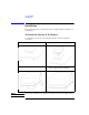
If the Semiconductor Relays on the Advanced window is set to PGU OPEN, the
selector channel makes the “PGU open” state during the test.
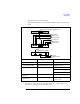
• Simplified circuit diagram
This figure shows a simple circuit diagram of the selector (selector expander).
The CH 1 and CH 3 circuits are different from the CH 2 and CH 4 circuits. Each
channel has one mechanical relay for SMU and one mechanical relay for PGU,
but the CH 1 and CH 3 circuits also have a semiconductor relay for PGU. The
relays are controlled by the 4155/4156/B1500A via the control circuit.
The semiconductor relay is useful when you need to perform a lot of switching
(for example, read/write tests of flash ROM) because the semiconductor relay is
more durable than mechanical relays.
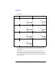
CH 1 and CH 3 can have four switching states: all open, SMU on, PGU on, and
PGU open. CH 2 and CH 4 can have three switching states: all open, SMU on,
and PGU on.