Agilent 16440A SMU/Pulse Generator Selector User’s Guide Agilent Technologies
Notices © Agilent Technologies 1994 - 2007 Warranty No part of this manual may be reproduced in any form or by any means (including electronic storage and retrieval or translation into a foreign language) without prior agreement and written consent from Agilent Technologies, Inc. as governed by United States and international copyright laws. The material contained in this document is provided “as is,” and is subject to being changed, without notice, in future editions.
This product complies with the WEEE Directive (2002/96/EC) marking requirements. The affixed label indicates that you must not discard this electrical/ electronic product in domestic household waste. Product Category: With reference to the equipment types in the WEEE Directive Annex I, this product is classed as a “Monitoring and Control instrumentation” product. Do not dispose in domestic household waste. To return unwanted products, contact your local Agilent office, or see www.agilent.
Safety Summary The following general safety precautions must be observed during all phases of operation, service, and repair of this instrument. Failure to comply with these precautions or with specific warnings elsewhere in this manual may impair the protections provided by the equipment. In addition, it violates safety standards of design, manufacture, and intended use of the instrument. Agilent Technologies, Inc. assumes no liability for customer’s failure to comply with these requirements.
Safety Symbols The general definitions of safety symbols used on equipment or in manuals are listed below. Instruction manual symbol: the product will be marked with this symbol when it is necessary for the user to refer to the instruction manual in order to protect against damage to the instrument. Indicates dangerous voltage and potential for electrical shock. Do not touch terminals that have this symbol when instrument is on. Protective conductor terminal.
User's Guide
User's Guide Agilent 16440A SMU/Pulse Generator Selector is one of the accessories available for Agilent 4155/4156 Semiconductor Parameter Analyzers and Agilent B1500A Semiconductor Device Analyzer. The selector is for automatically switching the measurement resource that is connected to a DUT pin. The measurement resource can be SMU, PGU, or SPGU. This manual consists of the following sections.
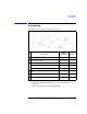
User's Guide Introduction Introduction The 16440A selector contains the following accessories. Description Agilent Part Number Quantity 16440A 1 1 SMU/Pulse Generator Selector 2 40 cm triaxial cable 04155-61605 2 3 1.5 m control cable (16440A-001) 04155-61612 1 3 m control cable (16440A-002) 04155-61611 1 40 cm control cable (16440A-003) 04155-61608 1 4 plate a 16440-60001 2 5 angle b 16440-60002 2 6 User's Guide c 16440-90005 1 a.
User's Guide Operation Operation The selector provides the automatic switching capability of the measurement resource SMU or PGU connected to a DUT terminal. This is useful for performing reliability testing (stress testing) of DUTs. For example, the selector can connect a PGU to the DUT for forcing ac stress, then can switch and connect an SMU for measuring dc characteristics. The selector has the channels CH 1 and CH 2 which provide the following conditions.
User's Guide Operation • Controlling the selector by using the B1500A Selector connections can be set by using the SMU/PG Selector tab screen of the Configuration window. And the PGU open can be set by using the Advanced window of the Measurement Setup. See the B1500A User’s Guide. If the Input/Output Path is set to Normally PGU (AUX) in the SMU/PG Selector tab screen, the selector performs automatic switching in every test.
User's Guide Operation • Switching state States CH 1 and CH 3 CH 2 and CH 4 All open SMU on PGU on PGU open The switching state of a channel is indicated by the green LEDs on the selector front panel. This table shows the relation of the relays and the LEDs for each switching state. The “PGU open” state is useful if a lot of switching needs to be performed. When the switching state changes from “PGU on” to “PGU open”, only the semiconductor relay switches.
User's Guide Operation • Connecting two selectors If you use two selectors to have four channels, connect the CONTROL Output terminal of the selector to the CONTROL Input terminal of the second selector using a 40 cm control cable as shown below.
User's Guide Operation • Connecting the selector to the 4155/4156 Turn off the 4155/4156 and 41501 before connecting the instruments. Then connect as shown below. 4155/4156 16442A/B Test Fixture 4 2 41501 16440A Selector 3 1 16440A terminal Cable Connect to CONTROL Input 16440A-001/002 Control cable 41501 To SMU/Pulse Generator Selector Interface Input SMU a 3.0 m or 1.5 m Triaxial cable 4156 HRSMU Force 4155 MPSMU Force 41501 MPSMU or HPSMU Force Input PGU a 3.0 m or 1.
User's Guide Operation • Connecting the selector to the B1500A Turn off the B1500A before connecting the instruments. Then connect as shown below.
User's Guide Installation Installation This section describes how to attach the selector to Agilent 16442A test fixture or to a shielding box. To Attach the Selector to Test Fixture You can attach your selector to the 16442A test fixture. You need a standard screwdriver. NOTE 1. Place the selector on your workbench. 2. Place the test fixture on top of the selector. 3. Position a plate on both sides. 4. Attach each plate using the three flathead screws supplied with the instrument.
User's Guide Installation The following steps apply when using two selectors. 5. Place the second selector on your workbench. Place the selector and the test fixture on top of the second selector. 6. Position a plate on both sides. NOTE 7. Attach each plate using the three flathead screws supplied with the instrument. If you use the 16445A selector adapter, fix it under the selector by similar method.
User's Guide Installation If you use the 16441A R-box, attach the R-Box to the selector as shown below. 16442A/B Test Fixture 16440A Selector 16441A R-BOX NOTE If you use the 16445A selector adapter, fix it under the R-box by similar method.
User's Guide Installation To Attach the Selector to Shielding Box You can attach your selector to a shielding box. You need a standard screwdriver. The following figure shows the spacing of the 16440A screw holes. You need to prepare four screws and nuts to match the screw holes.
User's Guide Installation If you use two selectors, connect selectors before attaching to the shielding box, as shown below. NOTE 1. Place the selector on your workbench. 2. Place the second selector on top of the selector. 3. Position a plate on both sides. 4. Attach each plate using the three flathead screws supplied with the instrument. If you use the 16445A selector adapter, fix it on top of the selector by similar method.
User's Guide Installation Attach the selector to the shielding box as shown below. 1. Attach an angle bracket to each side of the selector, using the screws supplied. 2. Place the selector(s) on the side panel of the shielding box. 3. Position four nuts on the inside panel of the shielding box. 4. Attach the angle bracket to the shielding box using four flathead screws.
User's Guide Installation If you use the 16441A R-box, attach the R-Box to the selector on the shielding box as shown below.
User's Guide Maintenance Maintenance This section provides the following maintenance information. • Cleaning • Servicing Cleaning the Selector To maintain high performance, the selector must be kept clean. Oil, perspiration, hair, dust, and dirt will degrade the board insulation, which increases leakage current and decreases measurement accuracy. Agilent Technologies recommend the following cleaning procedure. 1. Make sure that voltage or current is not present at any channel. 2.
User's Guide Maintenance Circuit Block Diagram 18 Agilent 16440A User’s Guide, Edition 5
User's Guide Maintenance Replaceable Parts When soldering, use low hydrochloric acid solder (Agilent part number: 8090-0433) to prevent the flux in the solder from spreading unnecessarily, and make sure that adjacent terminals are not bridged. After soldering, make sure that there are no lint bridges, which would increase the leakage current. Reference Designation Agilent Part Number Description R1 0757-0442 Resistor 10 kΩ, 1%, 0.125 W R6 0698-3440 Resistor 196 Ω, 1%, 0.
User's Guide Maintenance Reference Designation Agilent Part Number Description R13 0698-0085 Resistor 2.61 kΩ, 1% R15 0757-0279 Resistor 3.
User's Guide Specifications Specifications The “supplemental information” and “typical” entries, in the following specifications are not warranted, but provide useful information about the functions and performance of the instruments. The following specifications data is specified at 23 ± 5 °C and 50 % relative humidity. • Function Agilent 16440A switches either a SMU or PGU to the associated output port. You can expand to 4 channels by adding an additional 16440A.
User's Guide Specifications • Accessories (furnished). See Section 1 for details. • • • • Option 001 • 1.5 m control cable (Agilent part number 04155-61612) • 40 cm triaxial cable (Agilent part number 04155-61605) Option 002 • 3.
User's Guide Specifications Supplemental Information The following reference data is specified at 23 ± 5 °C (73 ± 9 °F) and 50 % relative humidity. • • SMU channel Leakage current less than 100 fA at 100 V Residual resistance 0.2 Ω typical Stray capacitance (force common) 0.3 pF typical at 1 MHz Stray capacitance (force guard) 15 pF typical at 1 MHz Stray capacitance (guard common) 130 pF typical at 1 MHz PGU channel Residual resistance 3.
User's Guide Specifications Agilent 16445A Selector Adapter Specifications Agilent 16445A Selector Adapter is the connection box required to transfer the control signal from the B1500A and apply DC power to the Agilent 16440A SMU/Pulse Generator Selector.